
Small DC Motor Speed Regulator

The circuit diagram of the motor speed regulator is designed to maintain a consistent motor speed in a portable tape recorder, irrespective of variations in load and supply voltage. The primary components of the circuit typically include an operational amplifier, a variable resistor (potentiometer), a transistor, and feedback mechanisms.
The operational amplifier is configured to monitor the voltage across the motor. It compares the actual speed of the motor, indicated by the voltage, with a reference voltage set by the potentiometer. This reference voltage can be adjusted to set the desired motor speed.
When the load on the motor changes, causing the speed to deviate from the set point, the operational amplifier outputs a control signal. This signal drives the transistor, which acts as a switch to adjust the power supplied to the motor. The transistor's duty cycle is modulated based on the feedback from the operational amplifier, ensuring that the motor receives the appropriate amount of power to maintain the desired speed.
Additionally, the circuit may include protective components such as diodes to prevent back EMF from the motor, which could potentially damage the circuit. Capacitors may also be present to filter noise and stabilize the voltage supply.
The overall design emphasizes efficiency and reliability, allowing the tape recorder to function optimally under various operational conditions. This motor speed regulator circuit exemplifies a robust solution for applications requiring precise speed control in small electronic devices.Reverse engineered circuit diagram of a motor speed regulator out of a portable pocket tape recorder containing a single motor for all functions. This circuit works amazingly well, keeping the motor speed constant regardless of shaft load and battery voltage.
🔗 External reference
Related Circuits
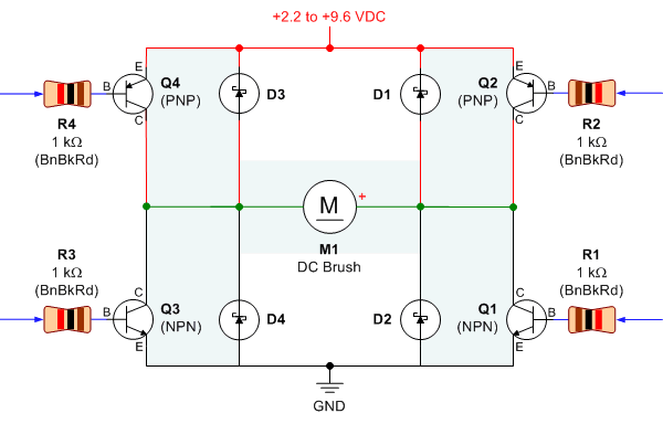
Control a small DC motor using an H-bridge with an Arduino Uno. The objective is to enable the motor to rotate in different directions based on left and right key presses on a keyboard. The provided code includes the...
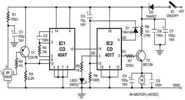
The following circuit illustrates an infrared toy car motor controller. This circuit is based on the 4047 and 4017 integrated circuits (ICs). Features: 16V. The infrared toy car motor controller circuit utilizes two primary integrated circuits, the 4047 and the...
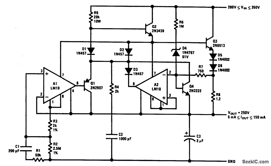
The output current is sensed across R8 and delivered to the current-limit amplifier through R7, where the foldback potential is developed by R6, with a threshold determined by D4. The specified values limit the peak power to below 20...
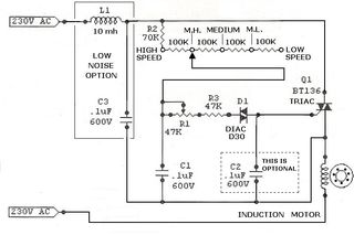
A small scroll saw is intended to be equipped with a cost-effective speed controller. The saw operates using an AC motor that seems to be brushless based on the examination conducted during disassembly. To design a speed controller for an...
The half-linear design allows for reduced thermal considerations, as the linear regulator only needs to handle 1-5W instead of the full 75W per rail. MOSFETs operate in their linear region, just below the rated voltage for RDS(on), but they...
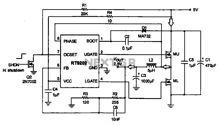
A 5V to 2.5V voltage regulator circuit is designed for use in computer motherboards. At its core, this circuit utilizes the RT9202 power management chip. The RT9202 functions as a switching pulse generating circuit, which, upon startup, converts a...