
Small Vacuum Tube Tesla Coil 2

The tube Tesla coil design integrates a 4X150 transmitting tube, which is known for its robustness and ability to handle high voltages. The forced air cooling mechanism is crucial for maintaining optimal operating temperatures, thereby preventing overheating during prolonged use. The choice of the oscilloscope transformer as the power supply is significant; it not only provides the necessary high voltage but also ensures a stable and reliable source of power. The 1 kV output is essential for achieving the desired electrical discharge characteristics typical of Tesla coils, while the 6.3 VAC supply is necessary for the tube's filament, ensuring it operates efficiently.
The absence of capacitors in this design is unconventional, as capacitors typically play a critical role in energy storage and discharge in traditional Tesla coil circuits. This unique approach may lead to different operational characteristics, potentially resulting in a more straightforward circuit with fewer components, thereby enhancing reliability and reducing the likelihood of component failure. The schematic diagram accompanying this description would illustrate the circuit layout, highlighting the connections between the tube, transformer, and other components, providing a visual representation of this innovative design.
This configuration may appeal to enthusiasts and engineers interested in experimenting with alternative Tesla coil designs, offering opportunities for further exploration and modification in high-voltage applications.This tube tesla coil was built inside a CPU power supply unit. It was first built on a workbench using components and jumpers for connections. The tube used is a 4X150 transmitting tube that used forced air cooling. An old oscilloscope transformer was used for the power supply, providing about 1kV for high voltage and 6. 3VAC for the filament suppl y. I experimented and played around with the circuit and came to this strange design that has no capacitors. Below is the schematic diagram. 🔗 External reference
Related Circuits
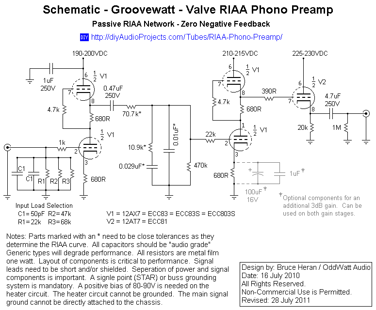
This project has been in development for over a year, initially postponed due to concerns about design complexity and the availability of high-quality phono preamps. The objective was to create a preamp that would deliver performance comparable to commercial...
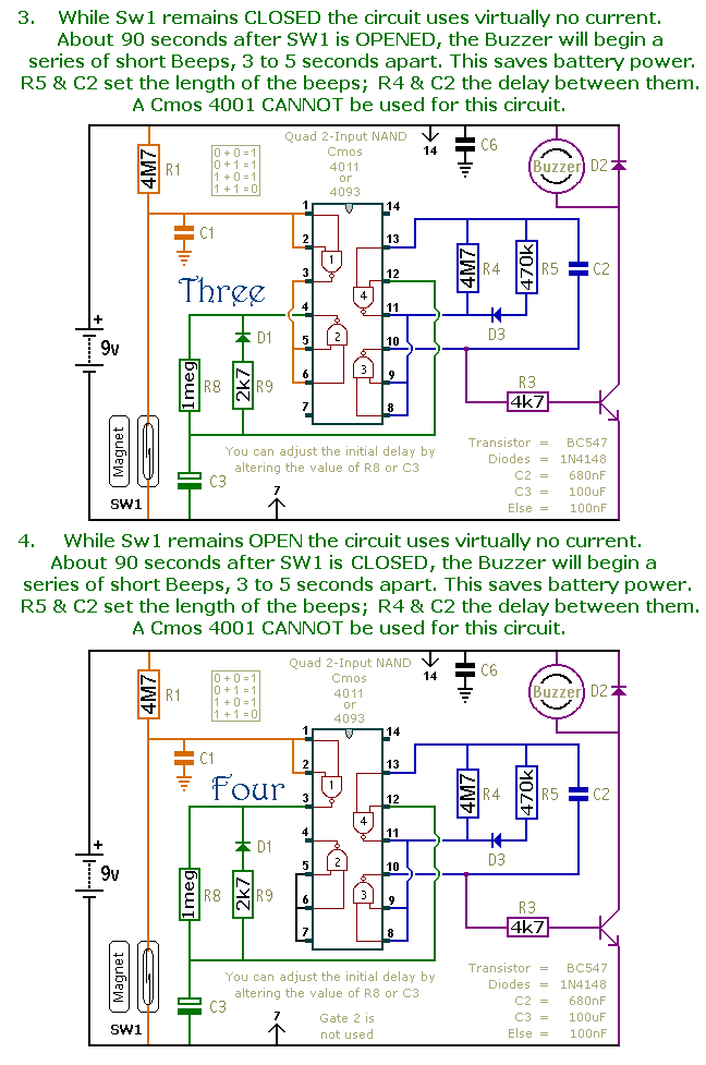
This is a collection of compact, self-sufficient alarm circuits designed for low standby current, making them ideal for battery operation. Some circuits are activated by normally-open and normally-closed switches, while others respond to variations in light or temperature. This...
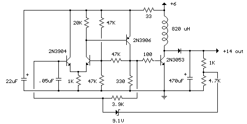
This compact switching power supply utilizes a Schmitt trigger oscillator to control a switching transistor, which delivers current to a small inductor. While the transistor is activated, energy accumulates in the inductor, and upon deactivation, this energy is released...
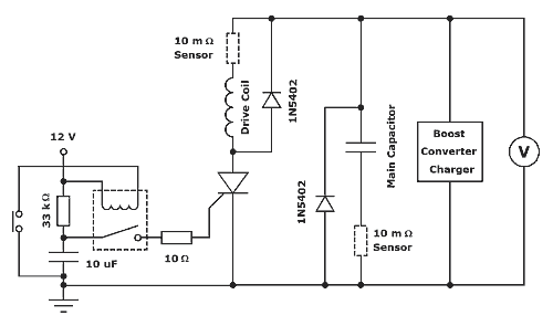
The thyristor-fired coilgun is a prevalent variant, primarily due to its high voltage and pulsed current capabilities. A diagram of the system designed for these experiments is presented in Figure 1. The thyristor utilized is an International Rectifier device,...
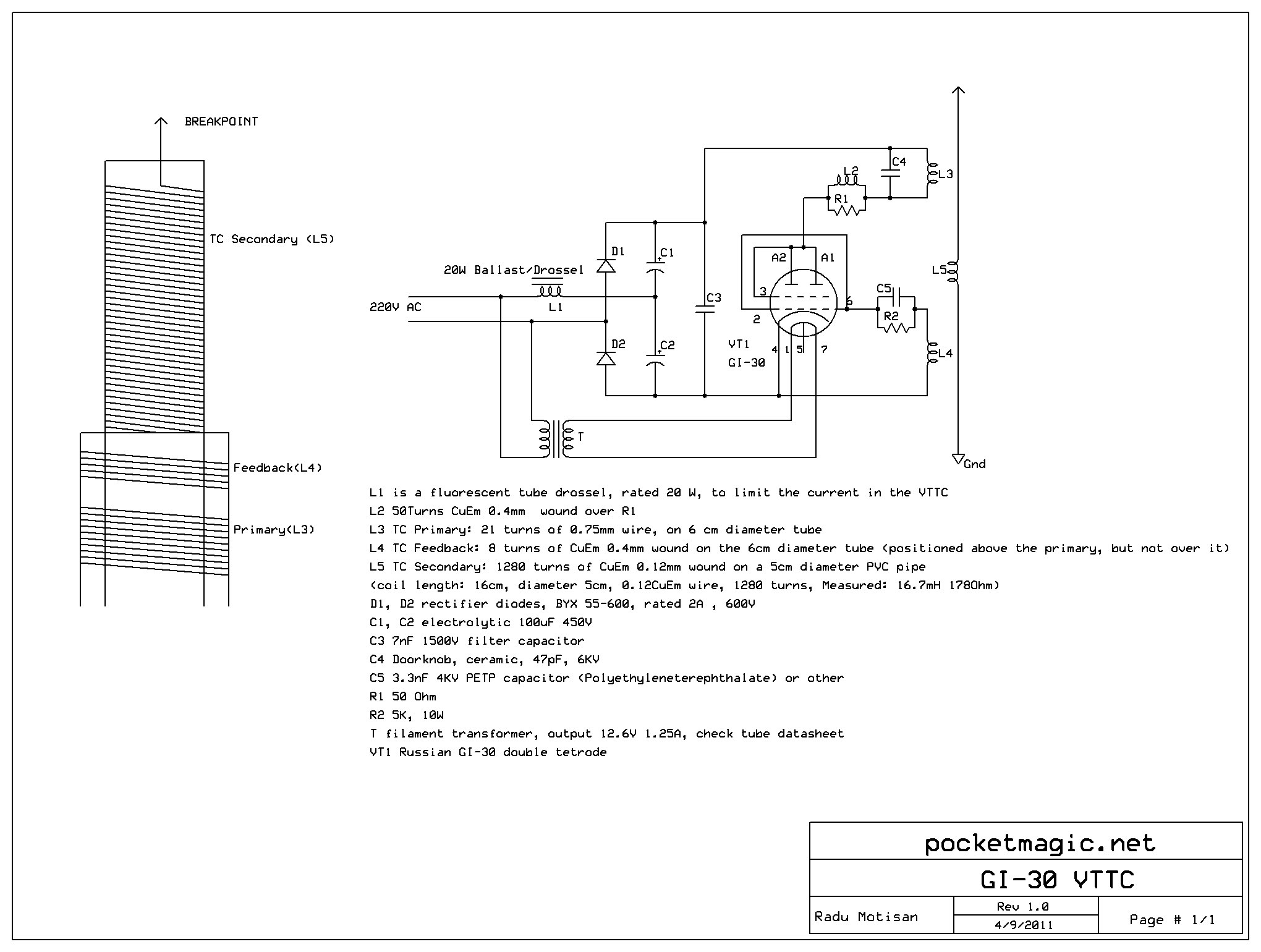
This setup is compact and operates offline directly from a 220V source, utilizing a voltage doubler to elevate the plate voltage to 560V DC. The circuit consists of a simple Armstrong oscillator, employing the feedback coil L4. The design...

The amplifier circuit utilizes the HA13118 IC, a Hitachi component designed to deliver 18 watts of output power. This integrated circuit operates as a Class AB amplifier. The HA13118 IC is a versatile audio amplifier designed for high-fidelity applications, providing...