
Small Variable Power Supply

The circuit described utilizes the LM723 voltage regulator, renowned for its reliability and simplicity in providing adjustable output voltage with over-current protection. The design allows for a variable output between 3 to 12 volts at a maximum current of 1 ampere. The resistor R2 is crucial as it sets the desired output voltage level, while R3 plays a pivotal role in defining the maximum current limit. The integrated circuit incorporates internal over-current protection that monitors the voltage across R3. When this voltage nears 0.65 V, the LM723 begins to disable the output, thereby preventing excessive current flow that could lead to component damage.
Capacitors C3 and C4 serve to stabilize the operation of the LM723. Their placement close to the IC is critical to mitigate potential oscillations, which the LM723 may experience under certain conditions. Direct soldering of these capacitors to the IC pins is recommended to minimize inductance and resistance in the circuit, ensuring optimal performance.
The operational range for the LM723 is from 9.5 V to 40 V for input DC voltage. Under conditions where the output voltage is not significantly lower than the input (specifically, within 6-7 V), the IC can provide a current output of up to 150 mA. However, when higher currents are required, an external pass transistor (T1) is employed in an emitter-follower configuration. In this configuration, T1 handles the majority of the load current, effectively offloading the LM723 and allowing it to maintain stable operation. The power dissipated by T1 is a function of the load current and the voltage difference between the input and output, necessitating careful thermal management to prevent overheating.
This circuit is well-suited for applications requiring a stable and adjustable DC power supply with built-in protection mechanisms, making it ideal for various electronic projects and devices.Features: 1. 3-12. 2 V, 1 A, over-current protection. This is a simple but reliable device based one of the oldest integrated voltage regulators of them all - the LM723. R2 sets the output voltage. The maximum current is determined by the value of R3: the over-current protection circuitry inside the LM723 senses the voltage across R3 and starts shut
ting the output stage off as soon as this voltage approaches 0. 65 V. This way the current through R3 can never exceed 0. 65/R3, even if the output is shorted. C3 and C4, both ceramic, must be placed as close as possible to the integrated circuit, because the LM723 can be prone to unwanted oscillations. It is not an overkill to solder them directly (and very carefully) to the pins of the IC. All other connections should also be kept short. The LM723 works with input DC voltages from 9. 5 to 40 V and the IC itself can source some 150 mA if the output voltage is not more than 6-7 V below the input.
When an external pass transistor is used (in the usual emitter-follower mode), the base-emitter junction of T1 represents a significant resistance and the integrated circuit`s output stage is relatively lightly loaded. All the current drawn by the load passes through T1 and it dissipates an amount of power that is directly proportional to the current and the difference between the input and the output DC voltage.
🔗 External reference
Related Circuits
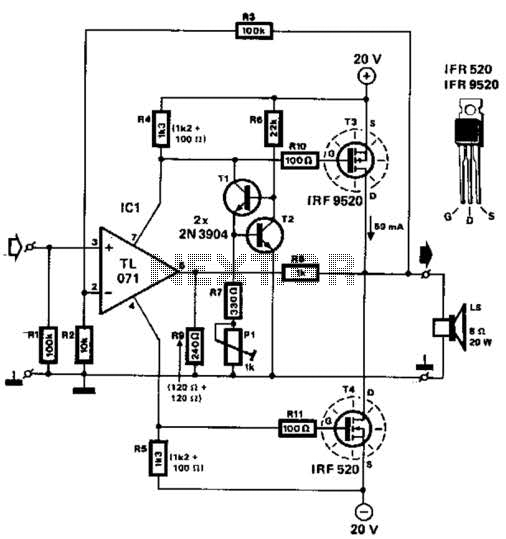
Two complementary MOSFETs are utilized to deliver 20 W into an 8-ohm load. A TL071 operational amplifier serves as the input amplifier. The MOSFETs must be equipped with a heatsink that has a thermal resistance of better than 5...
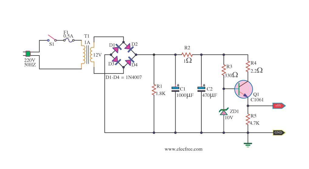
This is a DC power supply circuit designed to regulate 9 volts and provide a current output ranging from 1 amp to 2 amps. The circuit utilizes a modified TIP31 transistor, although alternative transistors such as TIP41, MJE3055, or...
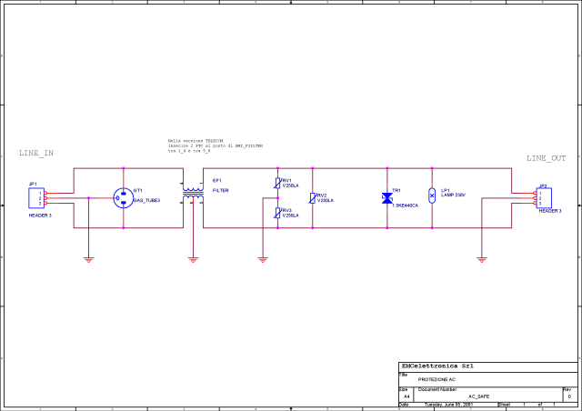
What is a circuit breaker? When is an AC power line filter or a phone line filter necessary? How can a noise filter be designed? Is it possible to create a homemade surge protector? The following circuit protection options...
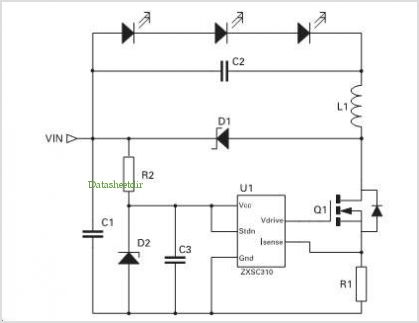
Application of the High Power LED Driver SP7652 with an Analog 0V-to-10V dimmer. Electrical Requirements: Input Voltage of 5.5V to 28V, Output Voltage VF of LED, Output Current ranging from 0 to 6A. This circuit is designed to provide...
A DC-DC power supply schematic is required that outputs a voltage between 12.7V and 14.5VDC, with an input voltage range from 12VDC upwards. The design of a DC-DC power supply capable of outputting a regulated voltage between 12.7V and 14.5VDC...
This design note presents a simple yet feature-rich 16-watt output, universal AC input adapter power supply for modems, hubs, or similar applications. The circuit utilizes a discontinuous mode (DCM) flyback converter topology designed around ON Semiconductor's NCP1027 monolithic current...