
DC/DC Power Supply Help

The design of a DC-DC power supply capable of outputting a regulated voltage between 12.7V and 14.5VDC from an input voltage that can start at 12VDC requires careful selection of components and configuration. This type of power supply is typically implemented using either a buck converter or a boost converter, depending on the specific requirements of the application and the input voltage range.
For a buck converter design, the circuit would include an input capacitor to stabilize the input voltage, an inductor to store energy, a switching element (usually a MOSFET), a diode for current flow direction, and an output capacitor to smooth the output voltage. The feedback control loop is essential for maintaining the desired output voltage; a voltage divider can be used to sense the output voltage and provide feedback to a PWM controller, which adjusts the duty cycle of the switching element to regulate the output.
In contrast, if the application requires a boost converter design—especially if the input voltage may be lower than the desired output voltage—similar components are used, but the configuration changes. The inductor is charged during the ON phase of the switch and releases energy to the output during the OFF phase, effectively stepping up the voltage.
In both designs, the choice of components such as the inductor value, capacitor ratings, and switching frequency will significantly affect efficiency and performance. Additionally, thermal management considerations must be addressed, as the switching elements can generate heat during operation. Proper heat sinking or thermal pads may be necessary to ensure reliable operation.
Overall, the schematic should include all necessary components, such as input and output capacitors, an inductor, a switching device, a diode, and a feedback loop with a PWM controller. The layout should minimize parasitic inductance and capacitance to enhance performance and reliability.Hi all, I am in need of a DC-DC Power supply schematic that outputs between 12.7 and 14.5VDC and an input that could be anywhere from 12VDC up to.. 🔗 External reference
Related Circuits
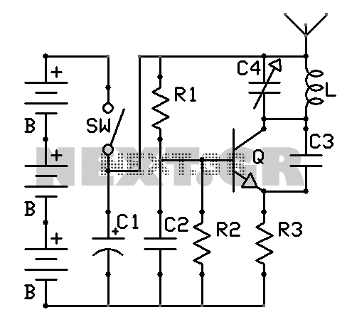
There are neighbors who may disturb you with loud televisions or radios. A solution is available. This jammer emits jamming waves that affect the TVs and radios in the neighborhood, so caution is advised. This device is an enhanced...
Utilizing a low-cost high-side precision current monitor to prevent excessive load currents from damaging power supplies. The implementation of a high-side precision current monitor is an effective strategy for protecting power supplies from excessive load currents. This type of current...
This is a light dimmer circuit. It does not include any special features and is a typical TRIAC-based dimmer circuit. This circuit is designed to operate with... A TRIAC-based light dimmer circuit is a common electronic design used to control...
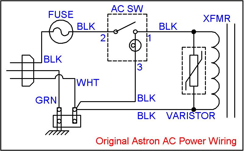
Owners of large 500-watt and higher Astron linear power supplies, as well as large HF amplifiers, are familiar with the "GNNNNnng" sound that occurs upon power-up. This noise is caused by the high inrush (surge) current flowing into the...
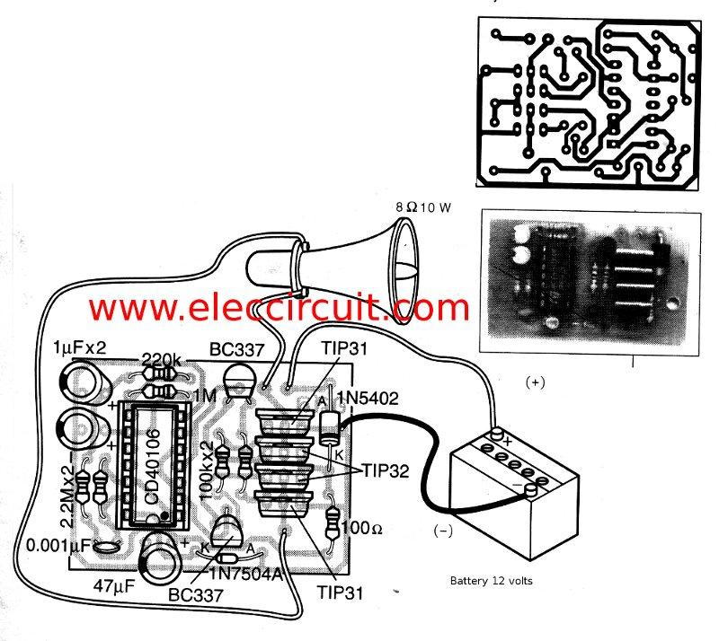
This is a simple siren sound generator with high power output and significant noise. The circuit utilizes digital ICs, specifically the CD4046, in an inverter configuration, along with four transistors to amplify the current output to a horn speaker...
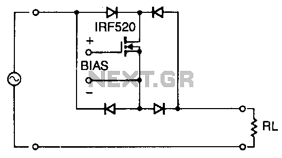
Utilizing four diodes in an array enables the use of a single MOSPOWER transistor for analog switching. The current flow is managed by maintaining the source-base connection of the MOSFET towards the load. It is essential to select diodes...