
Smart power grid demands innovative design

umer to provide real-time information on energy consumption and cost. The energy supplier`s biggest headache is catering for the peak loading on their electric network. Peak loads can be related to user demand, such as air conditioners in hot weather, or may be the result of equipment outages. The smart grid`s aim is to reduce the impact of peak loading both by changing user behavior and by directly controlling the consumer`s equipment.
By leveling out the network load, utilities can more efficiently manage their generating and transmission capacity, saving cost and reducing emissions. Deploying the smart grid should provide equitably priced electricity for all customers through enhanced security, quality, reliability, and availability of power.
Smart meters communicating with a smart network will allow the utility to implement a variety of control and incentive programs, such as real-time variable pricing. With features like in-home energy displays or eco-panels, the consumer can be warned when a peak loading rate is being charged.
They can then make an informed choice to switch off appliances such as dryers and postpone their use until a lower rate is available. With smart appliances or Demand Response Units (DRUs) controlling appliances in the home, the rescheduling of high consumption functions can be controlled directly by the utility via the smart meter.
The smart grid is no empty promise it is coming now and the energy savings are substantial. The Federal Energy Regulatory Commission (FERC) found that of the 140 million energy meters installed across the United States, 4. 7% are smart capable up from less than 1% in 2006. According to FERC, the potential demand-response energy savings from the use of smart metering is 41, 000 MW, or about 5.
8% of peak demand. Many states are introducing mandatory smart meter deployments through legislation and utility regulation. $28 billion is forecast to be spent over the next five years on electric transmission and distribution projects, much of it adding intelligence to existing systems.
In April 2009, the city of Miami announced plans to put more than 1 million wireless smart meters into every home and most businesses in the Miami-Dade area as part of the Energy Smart Miami initiative. The initiative includes a range of technologies to improve electricity delivery and help consumers manage their power usage, including the ability to log on to a Web site and review their power usage over time.
Load-control programs with meter-based controls were first introduced in the U. S. in 1968. Since then, several kinds of incentive-based programs have evolved. With direct load control, the energy supplier remotely shuts down or cycles a customer`s equipment to balance out overall consumption. The customer benefits from a rate discount for agreeing to reduce load during system contingencies. In Europe, the same process is occurring in many countries. According to the analyst company Berg Insight (Gothenburg, Sweden), the installed base for smart electricity meters in Europe will grow by 16% annually through 2014.
At the end of that period, the number of installed smart meters is expected to reach 96 million units. The U. K. government has announced plans to have smart meters installed in all 26 million U. K. homes by 2020. Government officials estimate the project will deliver net benefits of £2. 5 to £3. 6 billion over the next two decades in the form of lower bills and reduced costs for electric and gas companies.
The smart meter is envisioned to be at the center of a home information network, gathering data from smart appliances and communicating with the energy supplier (see Fig. 1). Many communications architectures are being considered, including mesh radio technology, power line modems, Ethernet, Wi-Fi, Bluetooth, and RS-485.
To accommodate differing regional and local requirements and standards, the communication handling in smart meters must be both flexible and upgradable. Security is also important to prevent unauthorized intrusion to consumer`s data. New regulations in the U. S. , Europe, and other regions require very low power consumption by the meter and place tight restrictions on standby power consumption.
Whatever the communications protocols employed, efficiency and power management within the meter are of prime importance. The power supply must work efficiently over a wide dynamic range with fast response to changing demands when transmitting data or fulfilling other functions.
This requires careful power circuit design. The power supply for a smart meter is typically required to deliver multiple 5- and 12-V outputs from universal 85 to 265 Vac with efficiency meeting California Energy Commission (CEC) / Energy Star EPS v2 and conducted EMI meeting CISPR22B / EN55022B. Figure 2 shows an example of a supply meeting these requirements. This circuit employs a Power Integrations LinkSwitch-CV switch-mode controller with an integrated 700-V MOSFET switch (U1).
The IC has protection features including auto restart for open/short faults and output open-circuit conditions, hysteretic thermal shutdown, and an extended creepage distance between high- and low-voltage pins on the package. The circuit employs a flyback configuration with the primary current passing through winding 1-3 of T1 and switched by the MOSFET in U1.
An RCD-R clamp (D5, R3, R4, and C3) limits the leakage inductance drain voltage spike. U1 employs a unique ON/OFF control scheme to provide output voltage regulation. The circuit requires no secondary-side control or optocoupler. The output is sensed by a feedback winding on the transformer. Despite the very low component count, a regulation of ±5% on the 5-V output and ±10% on the 12-V output is achieved across the full input voltage and load range. The pi filter (L1, L2, C1, and C2) minimizes conducted differential mode EMI. The circuit handles surges well and is designed to meet IEC950 and UL1950 Class II safety requirements.
The low component count enhances reliability. The 30% component reduction resulting from using primary-side control translates into a 22% decrease in FIT rate. – 🔗 External reference
Related Circuits
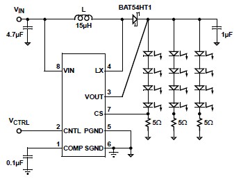
A simple white LED driver schematic can be created using the EL7513 constant current boost regulator, which is specifically designed for driving white LEDs. This driver can manage 4 LEDs in series or up to 12 LEDs in a...

In this circuit, a 2-MHz clock is divided by eight in U1, resulting in a stable 250-kHz carrier. Q1 and Q2 buffer the clock, providing a low-impedance drive for operational amplifier U4, which functions as a high-gain amplifier and...
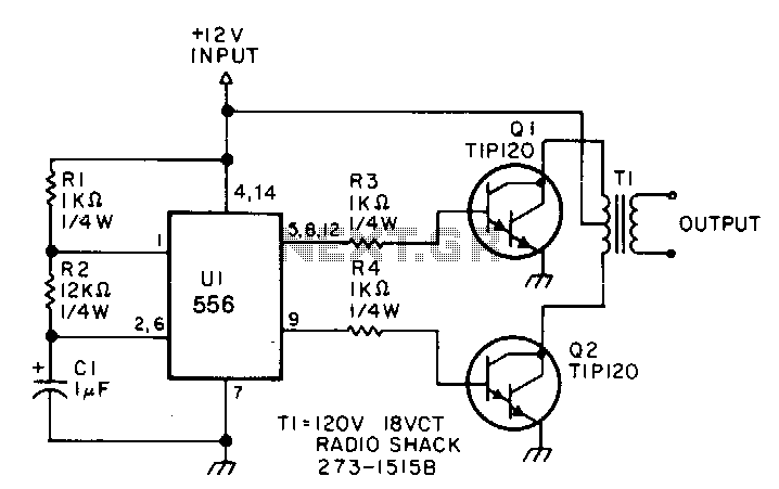
This low-power inverter utilizes only nine components to convert 10 to 16 VDC into a 60 Hz, 115 V square-wave output suitable for operating AC equipment with a maximum power of 25 W. The initial section of the 556...
All miniature electronic devices operate off batteries. Some of them require higher than the standard battery voltages for efficient operation. If a battery with the specific voltage is unavailable, additional cells must be connected in series to increase the...
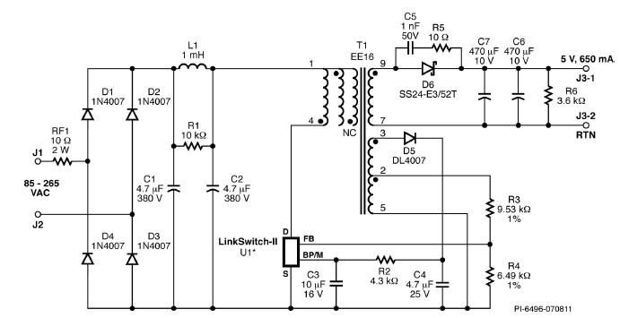
A simple 3.25W constant voltage/constant current (CV/CC) charger can be designed using the LinKSwitch family IC manufactured by Power Integrations. This electronic circuit project is intended to provide a 5-volt output with a maximum current of 650mA. The 3.25W...

This circuit utilizes two pairs of comparators from an LM339N quad comparator. One pair controls the yellow positive (+) and negative (-) indicators, while the other pair drives the red warning LED3. The circuit is powered by the unregulated...