
SMPS circuit

The flyback tester circuit employs an astable multivibrator configuration, which allows it to oscillate continuously without requiring any external triggering. The core components typically include two transistors, resistors, capacitors, and a transformer. The transistors are configured to alternately switch on and off, creating a square wave output that drives the primary winding of the transformer. The frequency of oscillation, around 90 kHz, is determined by the values of the resistors and capacitors in the circuit.
In practice, the circuit is powered by a 12 V DC supply, which is connected to the collector of the first transistor. The output from the secondary winding of the transformer is connected to the input of the circuit, allowing for testing of various transformer configurations. The voltage measurement at the primary winding can be performed using an AC voltmeter, which will indicate the output voltage generated by the oscillation in the transformer. A successful measurement will show a voltage within the specified range, confirming the operational integrity of the transformer.
In cases where the primary winding does not produce any voltage, further investigation is required, as this may suggest a fault in the transformer. The circuit can be modified to accommodate different transformer specifications by adjusting component values or transformer connections, making it a versatile tool for testing a wide range of transformers in electronic applications.Its a simple fly back tester, I believe you can built it, i use this circuit to test all of high freq transformer like SMPS transformer or fly back, this circuit is an astable multivibrator with about 90Khz freq, 12 vdc as vcc. To check SMPS transformer or fly back you should reverse the input and output, i mean you use secondary 12v or 24v out pu
t as input, give 12 or 24 output pin 12 vdc and another pin to output this circuit, when you turn on this circuit, use ac volt meter to measure primary, it should be come out 80 - 480 vac, depend to transformer spec, if there is no voltage come out from the primary transformer, so the transformer is damage, you can also measure another pin with the same step. 🔗 External reference
Related Circuits
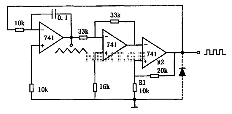
The circuit illustrated generates a variety of low-frequency waveforms, specifically triangle and square waves, simultaneously. It consists of several stages: the first stage is an integrator, followed by a gain stage with an inverter, and a comparator stage that...
This battery backup circuit can be integrated into surveillance systems or alarm controls to provide power during mains power failures. The battery backup will immediately take over the load without any delay, and the circuit is simple to construct....
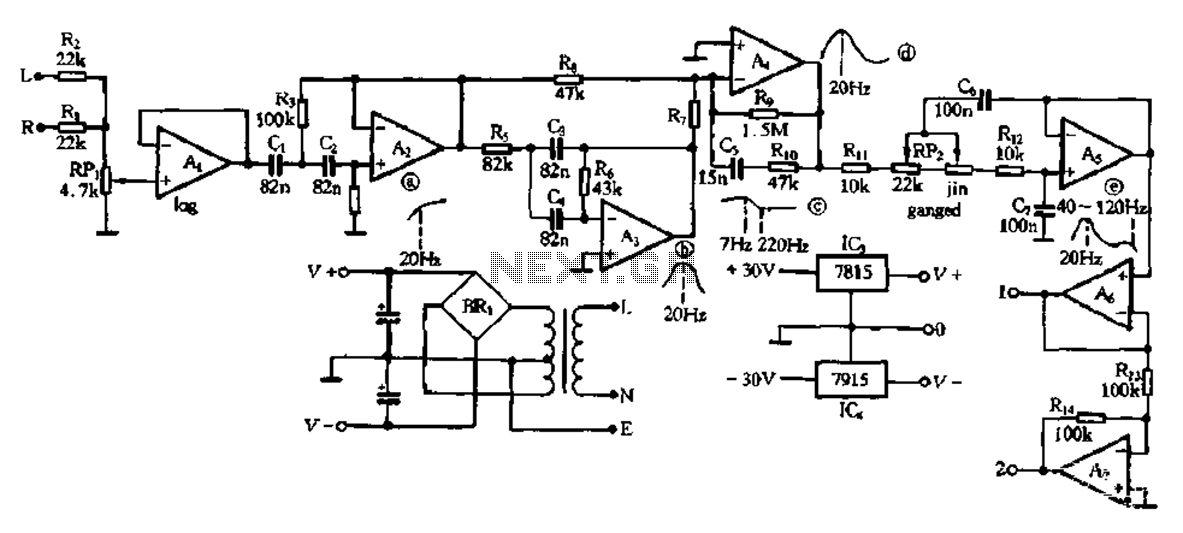
This electronic bass equalizer circuit utilizes two quad operational amplifiers, specifically the TL084 high-speed operational amplifier. The circuit includes left and right channels that are mixed through resistors R1 and R2, and features a total bass level adjustment potentiometer...

A basic LED driver circuit consists of a 5-volt power source, a 2 kΩ potentiometer, and an LED. The LED is forward biased, with the manufacturer specifying a maximum current rating of 20 mA at a diode voltage drop...
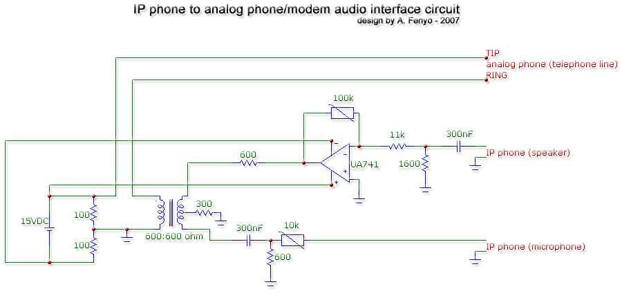
The transformer is a 600:600 ohm transformer, also referred to as a 1:1 ratio 600 ohm transformer. It has approximately the same number of turns on both the primary and secondary coils and is optimized for operation at a...
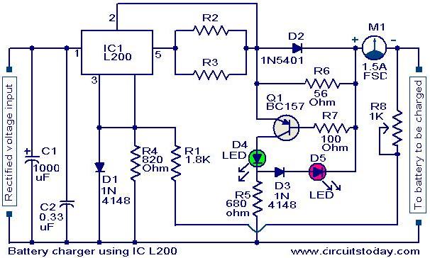
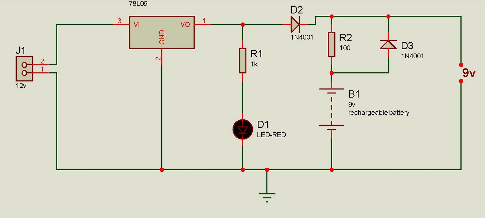
A simple battery charger circuit with reverse polarity indication is presented here. The circuit utilizes the L200 integrated circuit (IC), which is a five-pin variable voltage regulator. The charging circuit can be powered by DC voltage from either a...