
Battery charger circuit using L200

The battery charger circuit described employs the L200 voltage regulator, which is notable for its ability to provide a stable output voltage, essential for safely charging lead-acid batteries. The circuit configuration allows it to be powered from a DC source, typically provided by a rectifier setup that converts AC to DC voltage.
To optimize the charging process, the resistors R2 and R3 are chosen to set the desired charging current, which is critical for the longevity and health of the battery being charged. The use of a potentiometer (P1) allows for fine-tuning of this current, accommodating variations in battery condition and ensuring that the charging process is efficient and safe.
The inclusion of a reverse polarity protection mechanism is a significant safety feature. The circuit utilizes a transistor (T1) and a diode (D3) in conjunction with two LEDs (D4 and D5) to provide visual indicators of the charging status. The green LED (D4) illuminates when the battery is charging correctly, while the red LED (D5) serves as an alert if the battery is connected in the wrong orientation. This feature prevents potential damage to the battery and the circuit itself due to incorrect connections.
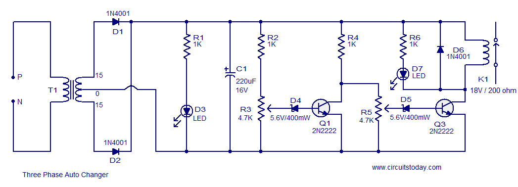
Overall, this battery charger circuit is designed with user safety and operational reliability in mind, making it suitable for charging 12 V lead-acid batteries in various applications. Proper selection of components and careful attention to circuit design principles ensure that the charger operates effectively within its intended parameters.A very simple battery charger circuit having reverse polarity indication is shown here. The circuit is based on IC L200. L200 is a five pin variable voltage voltage regulator IC. The charging circuit can be fed by the DC voltage from a bridge rectifier or center tapped rectifier. Here the IC L200 keeps the charging voltage constant. The charging curr ent is controlled by the parallel combination of the resistors R2 & R3. The POT P1 can be used to adjust the charging current. This circuit is designed to charge a 12 V lead acid battery. The transistor t1, diode D3 and LED are used to make a battery reverse indicator. In case the battery is connected in reverse polarity, the reverse polarity indicator red LED D5 glows. When the charging process is going on the battery charging indicator green LED D4 glows. 🔗 External reference
Related Circuits
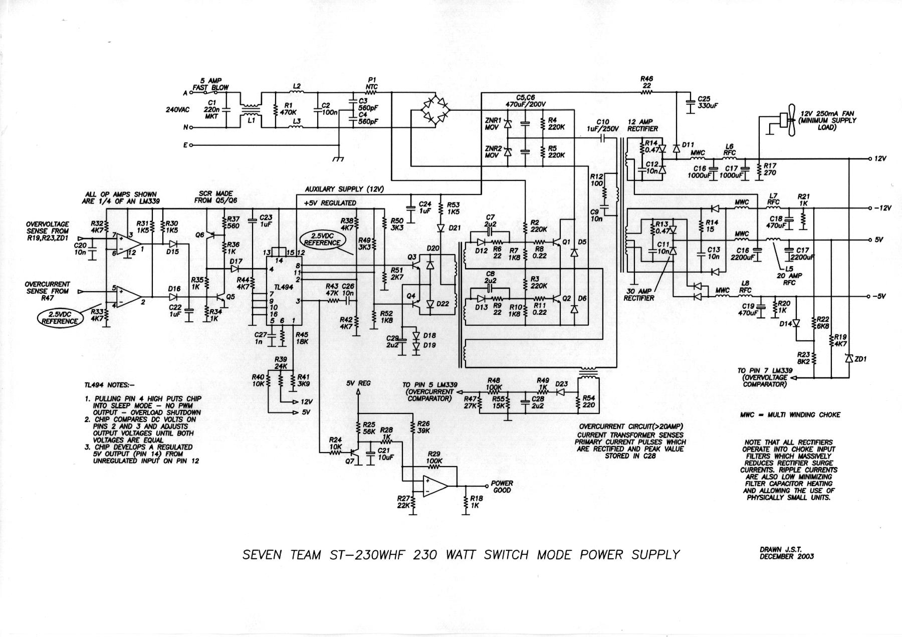
An even power device is designed to supply energy to a computer. It is typically intended for converting alternating current (AC) into low-voltage direct current (DC). Without this component, a computer is merely a collection of metal and plastic...
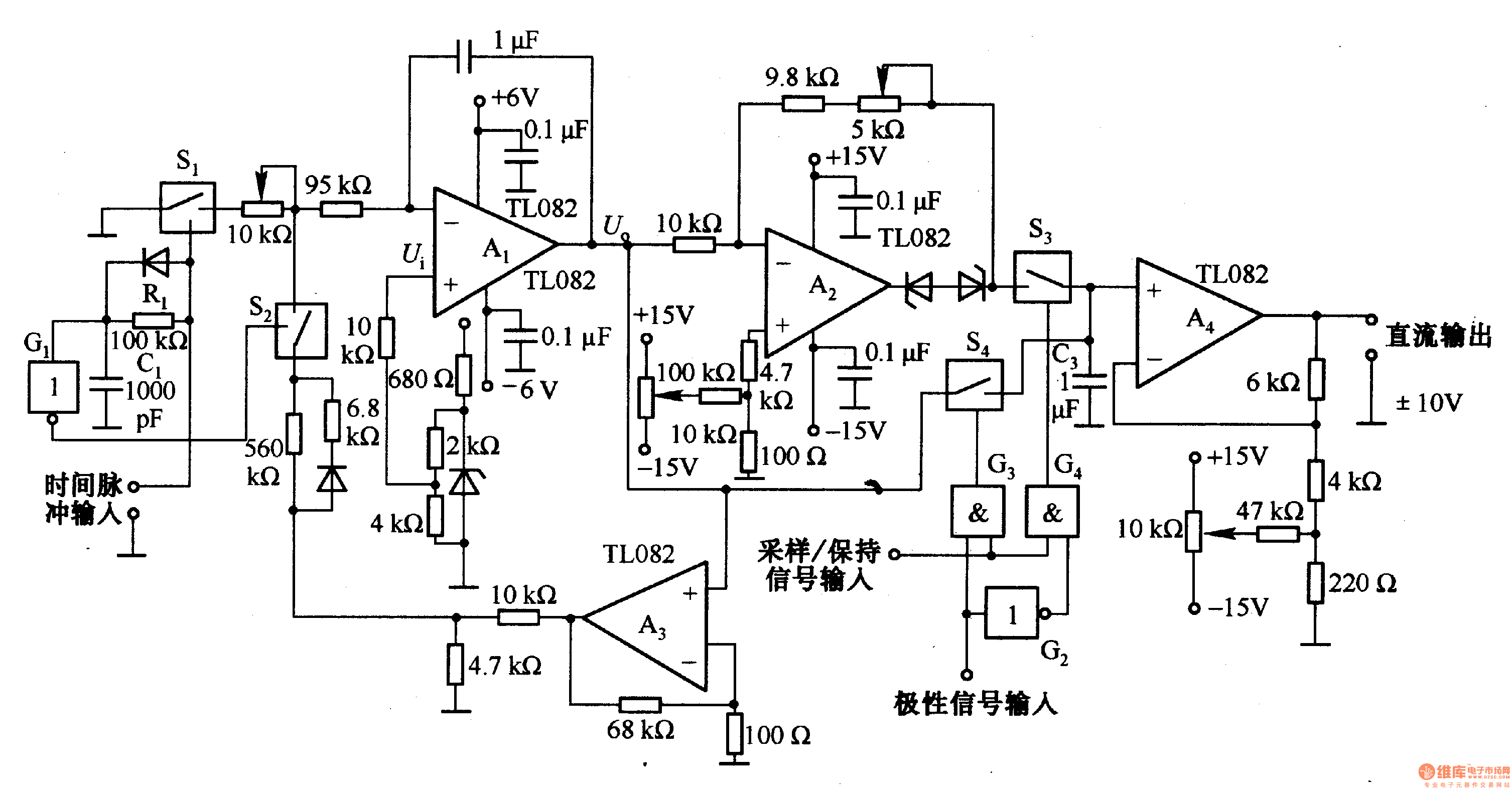
This circuit is designed for pulse width (time) to voltage conversion. According to the component parameters in the diagram, it can convert a pulse width of 0.1 seconds into an output voltage of 10V. When a conversion pulse is...
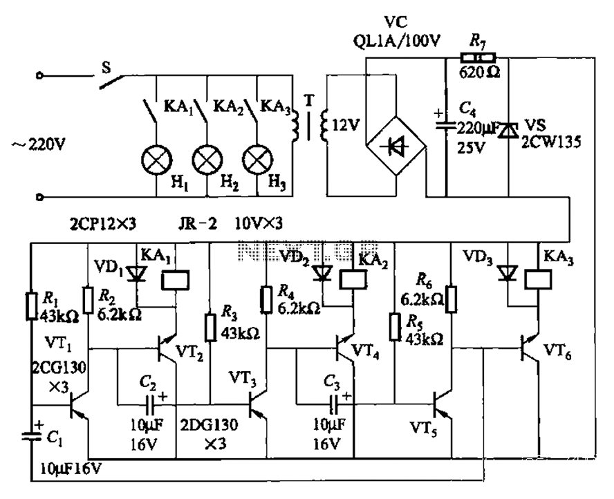
The transistors VTi, VT3, and VTs, along with the RC components, form three distinct multi-resonator oscillators. The oscillation frequency levels are dependent on the values of Ri, R3, Rs, and Cl, as well as Cz and C3s. The circuit comprises...
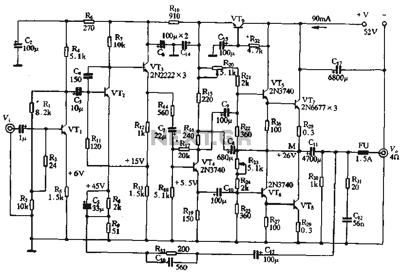
The circuit depicted in the figure is a highly technical OTL (Output Transformer-Less) amplifier circuit. It features a frequency response range of 10 Hz to 100 kHz and exhibits a total harmonic distortion of less than 0.1%, which is...
This circuit is a modification of a high and low voltage cut-off with delay and alarm circuit that was featured in Circuits Today. It has been tested and found to be reliable. The circuit can be adapted with minor...
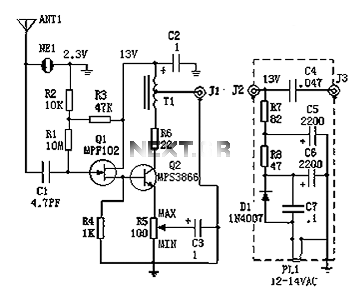
An active antenna operating within the frequency range of 100 kHz to 30 MHz, characterized by its compact size and effective performance. It is designed to be simple and low-cost, making it ideal for remote medium wave and short-wave...