
SN754410 Dual Motor Control Circuit

The SN754410 Dual Motor Control circuit operates effectively for applications requiring precise motor control. The circuit design incorporates a robust structure that allows for the simultaneous control of two DC motors or one stepper motor through the use of H-bridge configurations. The LM7805 voltage regulator ensures that the microcontroller and motor driver receive a stable +5V supply, which is crucial for reliable operation.
In this circuit, the PIC 18F452 microcontroller plays a vital role, as it processes analog signals from the sensors or user inputs and translates them into digital signals that control the motor operations. The use of PORTA pins for analog inputs allows for the integration of various sensors, enabling the system to respond to external conditions. The output pins on PORTD are strategically assigned to control the motor driver, facilitating precise control over motor speed and direction.
The SN754410 motor driver is designed to handle the necessary current for the motors while providing features such as braking and direction control. The enable pins ensure that the H-bridges are always active, but they can also be modified for dynamic control through the microcontroller if desired. This flexibility allows for advanced control strategies, such as PWM (Pulse Width Modulation) for speed regulation.
Overall, this circuit exemplifies a practical approach to motor control, combining simplicity with functionality. It is suitable for various robotics and automation projects where precise motor control is essential.The SN754410 Dual Motor Control circuit can be seen below. It is just about as simple as it looks with the PIC being the central processor. The main parts used and seen in the schematic below are the 7805, 18F452 and SN754410. The LM7805 +5v Regulator is used for its simplicity and the fact that the PIC uses the +5v digital standard. Since our motors are not too current demanding, this regulated supply will also be connected to the motor controller. The PIC 18F452 acts as the primary input and output control unit. It will be taking the analog input from PORTA pins 2 (RA0) and 3 (RA1), evaulating this input and then using PORTD, pins 19, 20, 21 and 22 to tell the motor controller what motors to move where and how fast.
The Motor Controller has 4 input pins 1A, 2A, 3A and 4A. The corresponding output pin for each half-h-bridge is marked with a Y (i. e. 2Y). The digital supply will be used for both signal and motor control so Vcc1 and Vcc2 are tied to the +5v regulated power. Finally, two Enable pins (pin 1 and pin 16) are connected to +5v through a 10k © resistor so these h-bridges are always enabled.
You could alternatively connect this to an I/O pin on the PIC to control these enable bits, but for simplicity I have not done that here. 🔗 External reference
Related Circuits
This circuit can be utilized in various devices to extract residual energy from seemingly depleted batteries. It is possible to connect multiple dead batteries in order to maximize energy extraction. This circuit design, often referred to as a Joule Thief,...
This digital volume control has no pot to wear out and introduces almost no noise in the circuit. Instead, the volume is controlled by pressing UP and DOWN buttons. This simple circuit would be a great touch to any...
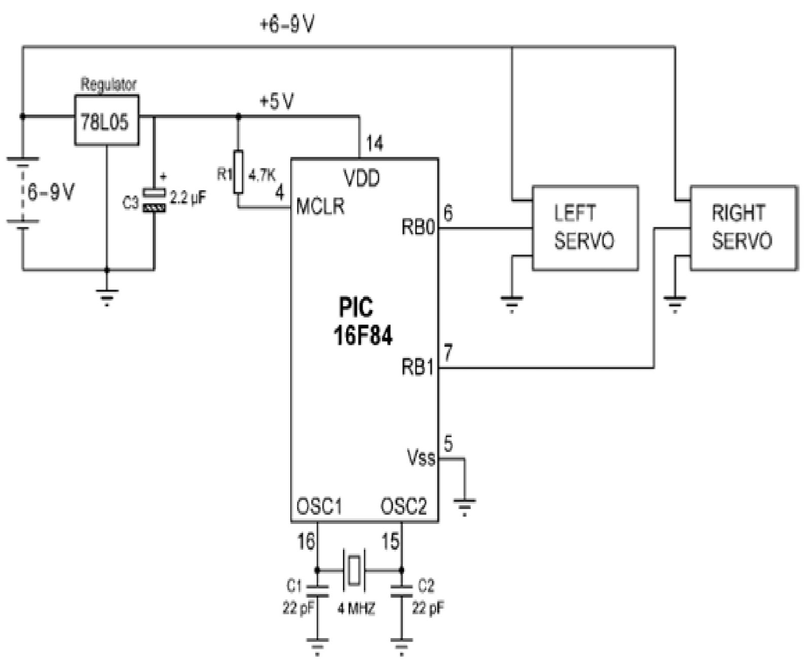
Mobile robots are utilized in various industrial, commercial, research, and hobby applications. This project focuses on controlling a mobile robot using servomotors. The robot is based on a well-known mobile robot called Boe Bot, developed by Parallax. The basic...
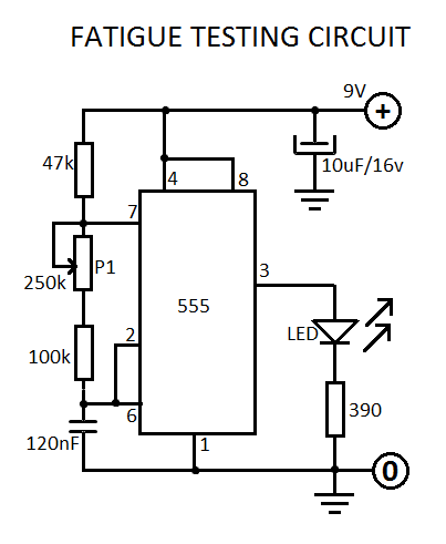
This fatigue testing circuit is straightforward and easy to assemble, designed to assess an individual's level of fatigue. Research indicates that the highest light frequency can be used as an indicator. This fatigue testing circuit operates on the principle of...
This circuit is similar to the previous one but employs positive feedback to enhance the amplitude delivered to the speaker. It was adapted from a small five-transistor radio that utilizes a 25-ohm speaker. In the prior circuit, the load...
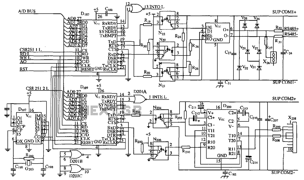
As shown in the figure, D187 is a universal asynchronous receiver-transmitter (UART). Its RX/TX signals are received through optocouplers N21, N22, and N29, facilitating RS-485 communication. The interface receiver/transmitter D28 and microprocessor D211 are completely optically isolated. D197 serves...