
Fatigue Testing Circuit

This fatigue testing circuit operates on the principle of light frequency detection, which is correlated with a person's fatigue levels. The circuit typically employs a light sensor, such as a photodiode or phototransistor, which detects variations in light intensity. The output from this sensor is processed through an analog-to-digital converter (ADC) to quantify the light frequency.
The circuit may include a microcontroller that interprets the ADC readings and applies algorithms to determine fatigue levels based on predefined thresholds. These thresholds can be calibrated based on empirical data gathered from user tests, allowing for a more accurate assessment of fatigue.
Additionally, the circuit could feature a simple user interface, such as an LED indicator or an LCD screen, to display the results. The LED could change color or blink at varying rates to indicate different levels of fatigue, while an LCD could provide a numerical representation.
Power supply options for the circuit may include batteries or a USB power source, ensuring portability and ease of use. The layout of the circuit should be designed to minimize noise and interference, particularly in the connections between the light sensor and the microcontroller.
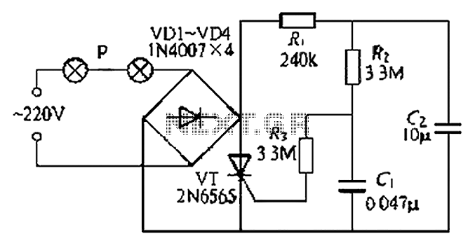
In summary, this fatigue testing circuit serves as a practical tool for assessing fatigue levels through light frequency analysis, utilizing basic electronic components to achieve its functionality.This fatigue testing circuit is very simple and easy to build and will determine how tired a person is. It has been discovered that the highest light frequ.. 🔗 External reference
Related Circuits
This circuit operates at potentially lethal 220V AC mains voltage. The circuit should be built and used only by individuals who know how to safely work with such dangerous voltages and how to construct the circuit to ensure safety....
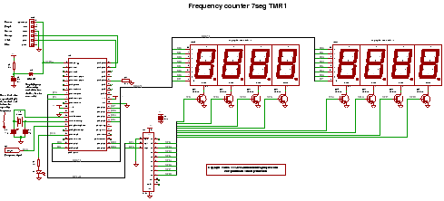
C code for a frequency counter circuit operating up to approximately 50 MHz, utilizing a multiplexed seven-segment display and employing Timer 1 to count the edges of the input signal. The frequency counter circuit described operates effectively within the range...

The circuit utilizes a transistor (VT) and a voltage regulator (VSL) to create a constant current source, employing three regulators to enhance the performance of the regulator circuit. The described circuit employs a transistor (VT) in conjunction with a voltage...
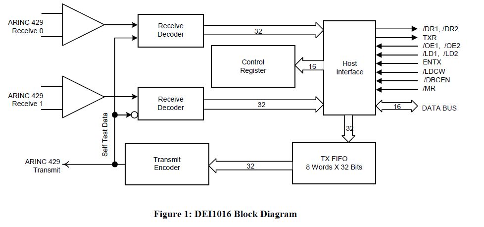
This document outlines the process of interfacing an Arduino with an ARINC 429 transceiver, illustrating the general methodology for connecting an Arduino to electronic circuits that can be applied to individual designs. The ARINC 429 bus is the predominant...
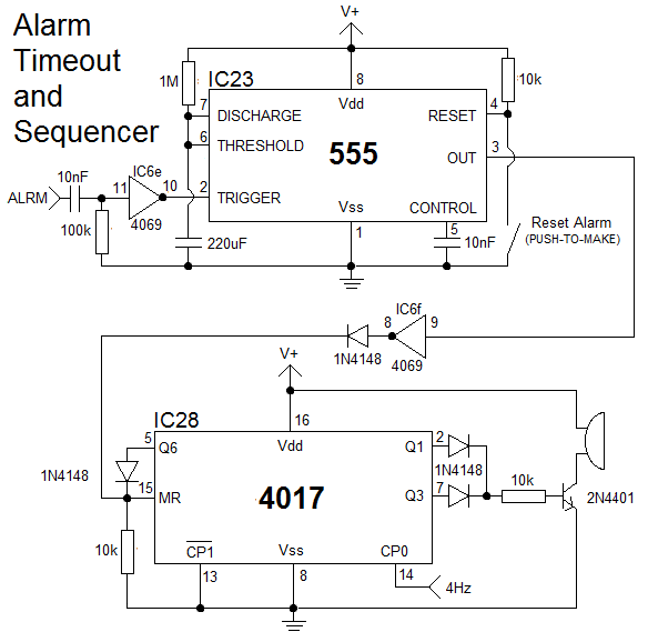
The clock is constructed using 25 CD4000 integrated circuits (ICs), three 555/556 ICs, and several discrete components. It features an alarm and a method for setting the time that is typically only seen in microcontroller designs. The complexity of...
A simple and easy-to-implement one-way flashing lights string controller is designed for small shop or home decoration. This device utilizes a thyristor-based dimmer circuit, which operates effectively by managing large capacitance. The circuit includes a ten-microfarad capacitor connected to...