
Sobriety Tester with LM3914


The described circuit is a reaction time tester that utilizes a combination of switches, resistors, a capacitor, and light-emitting diodes (LEDs) to visually represent the user's reaction time. The primary components include a switch S1, which acts as an initial trigger, and switch S2, which serves as the secondary trigger. The circuit is designed to measure the time interval between the release of S1 and the activation of S2.
When S1 is depressed, the circuit is initially in a state where S2 is closed. Upon the tester's command, the user releases S1 and subsequently toggles S2 to open. This action initiates the charging of capacitor C2 through resistors R1 and R2. The charging process continues until S2 is opened, at which point the current flow is interrupted. The voltage across C2 accumulates in direct relation to the duration of the reaction time, meaning that longer reaction times result in higher voltages.
The circuit is designed to light up a series of LEDs, with the number of LEDs illuminated corresponding to the voltage level across C2. This provides a visual indication of the user's reaction time. For calibration purposes, R1 can be adjusted to ensure that a sober individual lights a low-numbered LED, while individuals with slower reaction times due to alcohol consumption will light higher-numbered LEDs.
To reset the circuit for subsequent tests, a third switch, S3, is included to discharge capacitor C2. The circuit can operate with various supply voltages, including 9V, 12V, 15V, or the specified 18V, making it versatile for different applications and setups. Overall, this circuit serves as an engaging tool for both entertainment and informal assessment of reaction times, particularly in social settings where alcohol consumption may be present.With all the holidays upon us, understandably some of us will be drinking alcoholic beverages. This circuit can be used as a guideline how much you have had to drink and how good your reaction time is. This circuit does not tell you whether you are over the legal limit of alcohol in in your blood. This circuit can also be use for fun to test your reaction time. The circuit works as follows. Imagine for the moment that S1 switch is depressed which causes it to be open and S2 switch is closed.
On command from someone acting as the tester, the person depressing S1 must remove his/her hand from the switch S1 and with the same hand toggle switch S2 to the open position.. When S1 is released, charging current begins to flow into capacitor C2 through R1 and R2. This current is interrupted, however, as soon as S2 has been opened. C2 will have accumulated a voltage directly proportional to the reaction time, which is the interval between S1's release and the opening of S2. Longer times create higher voltages and cause higher numbered LED's to light. For example, a sober person might react quickly enough to light LED 2 or LED , while someone truly sloshed will light up to LED 10.
To run another test, discharge C2 with S3, then press S1 and, finally, close s2 once more. R1 should be adjusted so that a sober person lights one of the low numbered LED's. The supply voltage says 18 volts but 9, 12, or 15 will work fine also. 🔗 External reference
Related Circuits

When a remote control fails to operate, the issue is often fundamental: the device does not emit light. Possible causes include dry solder joints, faulty LEDs, or a depleted battery, potentially due to a stuck button. The human eye...
The Eico 666 is a capable tube tester whose functionality can be expanded with a modest investment of time to understand its schematic, operational regimes, and methods for adding new functionalities. This tester is known for supplying sufficient voltages...
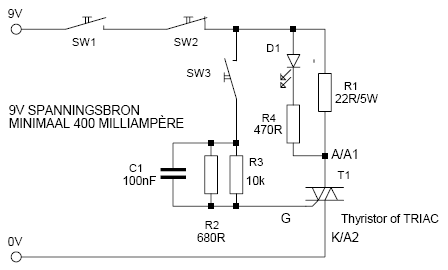
This is a simple but effective thyristor TRIAC tester. Operation at a good thyristor/triac: LED lights when SW3 is pressed. LED turns off when SW2 is pressed. If this occurs, the thyristor/triac is OK. Tip: Hirschmann clips for the...

This circuit is designed to test zener diodes. It connects to a 120V AC line and amplifies the output. The zener diode testing circuit operates by utilizing a transformer to step down the 120V AC line voltage to a more...
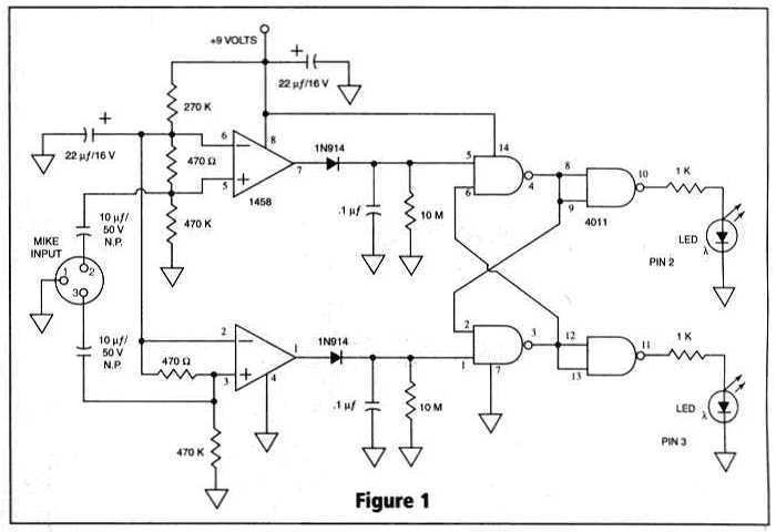
Many things can go wrong in a modern recording studio, but few are as difficult to track down as reversed microphone polarity. When a microphone is placed in front of a sound source, a positive pressure on its diaphragm...
This is a simple servo tester which will comprehensively test the capabilities of almost any modern servo. It has two pushbuttons, CENTRE and SWEEP and a potentiometer which works as follows: CENTRE Does exactly that, centers the servo, afterwards...