
Soft Start For Amps

The circuit in question involves a transformer-based power supply system, where the delay time is critical for the proper functioning of the connected load. The specified delay time of approximately 100 milliseconds allows for adequate stabilization of the circuit, ensuring that the transformer can handle the inrush current without damage. Specifically, this delay accommodates about five full cycles at 50Hz or six cycles at 60Hz, which is essential for the operational integrity of the system.
The transformer is designed to operate under significant inrush current conditions, where it can withstand 200% to 500% of its rated full load current during start-up. This characteristic is particularly important because, without a soft-start mechanism, the inrush current can exceed 50A for 240V transformers, potentially leading to overheating or damage to circuit components. The revised formulae for calculating these parameters take into account the high inrush currents that are common in transformer applications.
Regarding the power supply for amplifiers, the ideal scenario would involve a standard 12V supply, which would simplify the design and component selection for relay systems. However, the reality is that most amplifiers operate with higher DC supply voltages, typically ranging from +/-25V to +/-70V. This variability complicates the selection of relays, as standard components may not be rated for these higher voltages. Therefore, careful consideration must be given to the choice of relays, ensuring they are adequately rated for the specific voltage levels encountered in the application.
In summary, the circuit design must account for the delay time, inrush current, and power supply voltage variations to ensure reliability and performance in transformer-based power systems. Proper engineering practices should be employed to mitigate risks associated with high inrush currents and to select appropriate components for the given voltage levels.The delay time for all circuits shown has been revised. The optimum is around 100ms - sufficient for around 5 full cycles at 50Hz, or 6 cycles at 60Hz. It is also quite alright to run the transformer to around 200-500% of full load current at start-up, and the formulae have been revised for 200%. Without the soft-start, inrush current can be so high as to be limited only by wiring resistance - in excess of 50A is not at all uncommon for 240V transformers.
If a 12V supply were to be available in all power amps, this would be very simple, but unfortunately this is rarely the case. Most amps will have DC supplies ranging from +/-25V to about +/-70V, and any attempt to obtain relays for these voltages will be
🔗 External reference
Related Circuits
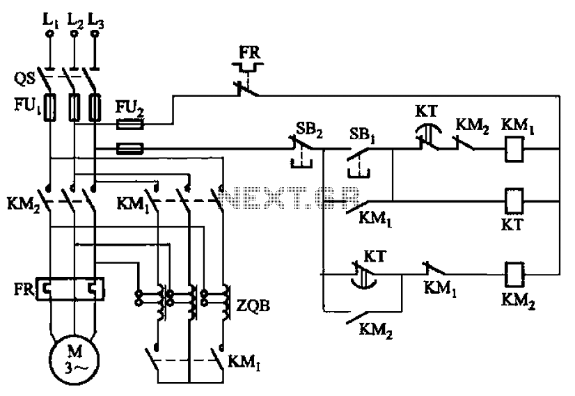
The circuit depicted in Figure 3-49 illustrates an autotransformer that is controlled by a time relay (KT). The delay time set by the KT relay corresponds to the motor's startup duration. The circuit utilizes an autotransformer, which is a type...
A switching power supply that has an output voltage significantly lower than its input voltage exhibits a unique characteristic: the current drawn from the supply is less than the output current. However, the input power (UI) is, naturally, greater...

Two soft start power supplies. The output voltage slowly increases to the desired output. The output voltage rises slowly and reaches 15 V in 5 seconds. In order to perform this soft-start function, the LM317 voltage regulator IC requires...
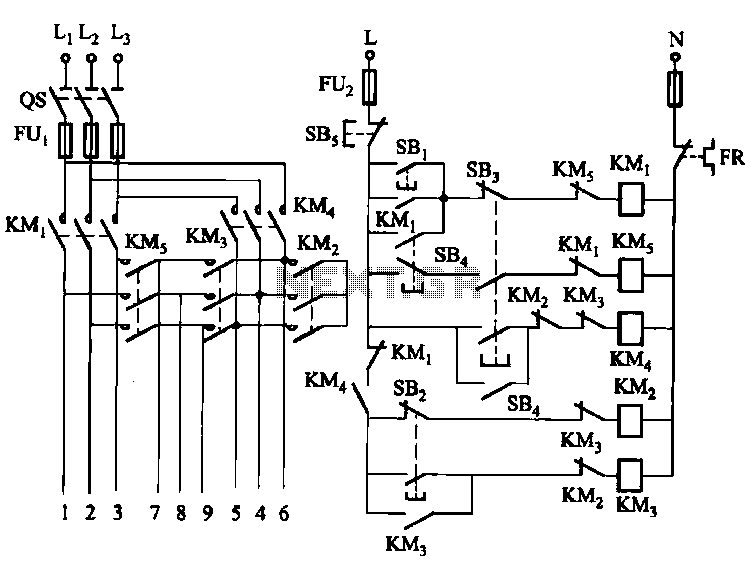
The circuit illustrated in Figure 3-62 is a manually controlled step-down start button circuit. Upon startup, the initial motor windings are configured in a Y-shape. Subsequently, the configuration transitions to a Yanbian shape (2:1), followed by a Yanbian shape...
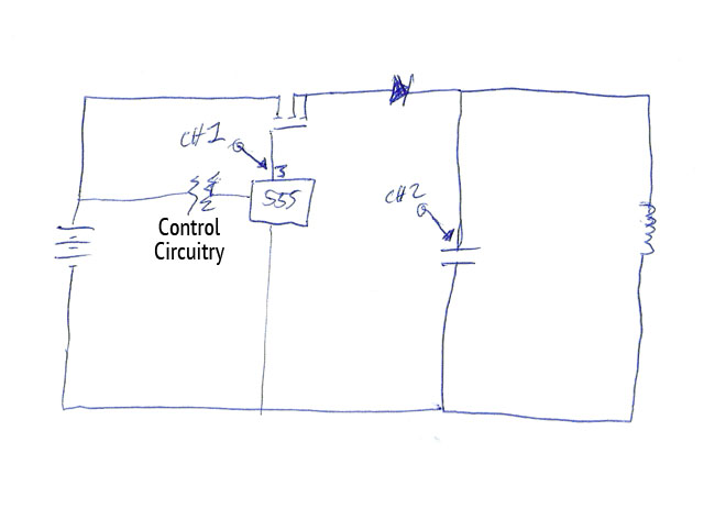
The top channel represents the signal to the gate of a MOSFET, which is controlling a tank circuit consisting of a large coil wrapped around ferrite and a 5µF capacitor. The coil's size results in an operating frequency close...
We are going to build a START-STOP drive (as commonly found in professional tools), that is a circuit with one switch to run the output (an LED in this case) and one switch to stop it. Nutchip feature two...