
Auto-voltage starting time relay control circuit

The circuit utilizes an autotransformer, which is a type of transformer that has a single winding that acts as both the primary and secondary winding. This configuration is beneficial for voltage regulation and provides a means to adjust the voltage supplied to the motor during startup. The time relay (KT) is a critical component in this circuit, as it determines the duration for which the autotransformer remains operational.
When the motor is powered on, the KT relay initiates a delay that allows the motor to gradually reach its operational speed. This delay is crucial because it helps to prevent inrush current, which can be detrimental to both the motor and the electrical supply system. The relay is calibrated to match the specific startup time required by the motor, ensuring optimal performance and protection.
As the motor accelerates, the relay monitors the elapsed time and will eventually deactivate the autotransformer once the set delay has expired. This transition is essential for switching the motor to full operational voltage, allowing it to run efficiently without the limitations imposed by the autotransformer.
In summary, the circuit in Figure 3-49 effectively integrates an autotransformer with a time relay (KT) to control the startup process of a motor, providing a reliable method for managing voltage and protecting against excessive current draw during the initial startup phase. Circuit shown in Figure 3-49. The circuit autotransformer out of operation by the time relay KT control. KT delay time is equal to the motor start-up time. Circuit shown in Fig ure 3-49. The circuit autotransformer out of operation by the time relay KT control. KT delay time is equal to the motor start-up time.
Related Circuits
The hum noise is produced by an electronic device with improper design. To address this issue, it is essential to identify the source of the hum. This involves checking the grounding, cabling, casing, and other factors that may contribute...
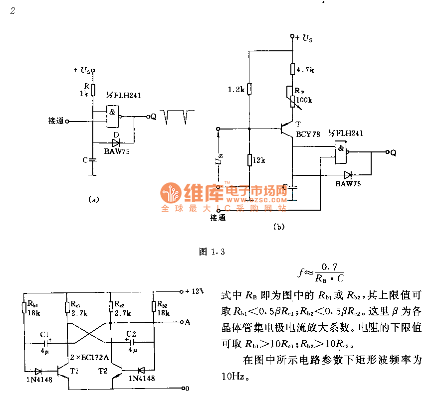
The circuit consists of two components whose parameters and models are designed to simultaneously generate a rectangular wave with a duty cycle of 1:1. The frequency is defined by the equation f = 0.7/(RB * C), where RB refers...
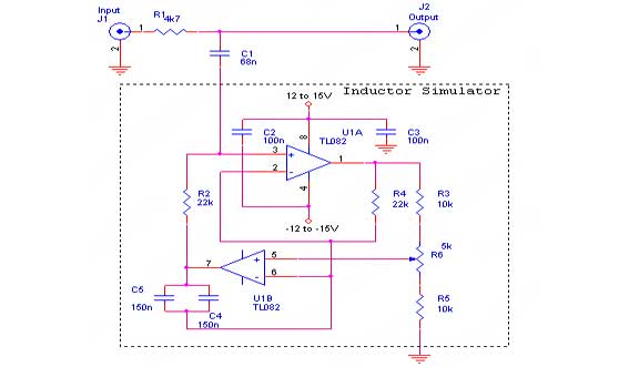
This sound effects circuit is designed to function as a signal distorter. When utilized with an electric guitar, it enables the creation of unique sound effects. The sound effects circuit operates by manipulating the input audio signal from the electric...
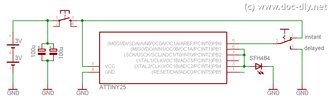
This site explains the process of constructing a low-cost DIY Canon RC-1 infrared remote control clone utilizing an AVR microcontroller. The project involves creating a remote control that mimics the functionality of the Canon RC-1, which is used for triggering...
Logic power control of an analog regulator can be useful in applications where a digital circuit or controller needs to manage a power source, such as in EEPROM. In electronic systems, managing power effectively is crucial for the performance and...
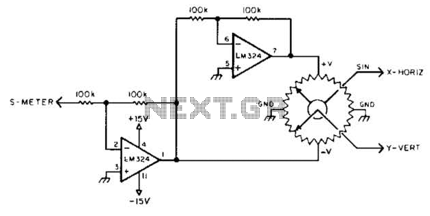
To display polar quantities, which include both the magnitude and direction of a received radio signal, a sine and cosine voltage proportional to an angle corresponding to the antenna direction is required. This setup utilizes a sine-cosine potentiometer connected...