
SOLAR BATTERY CHARGER CIRCUIT WITH OVER CHARGE PROTECTION

The solar battery charging circuit with overcharge protection is designed to harness solar energy efficiently while ensuring the longevity of the battery. The solar panel, composed of multiple solar cells, converts sunlight into DC electrical energy. The output voltage from the solar panel is variable, depending on the intensity of sunlight. This voltage is directed towards the battery for charging.
The LM723 voltage regulator plays a crucial role in this circuit. It is configured to monitor the voltage level of the battery. When the battery voltage reaches a predetermined threshold, indicating that it is fully charged, the LM723 activates. This action turns on the MJ1000 NPN transistor, which effectively shorts the solar panel's output to ground. By doing this, the circuit prevents any further charging of the battery, thus protecting it from potential overcharge damage.
In addition to the LM723 and MJ1000, the circuit may include supporting components such as diodes to prevent reverse current flow, capacitors for filtering, and resistors for setting the reference voltage for the LM723. The overall design ensures that the solar panel can continuously charge the battery under optimal conditions while safeguarding it from overvoltage scenarios.
The implementation of this solar battery charging circuit is ideal for applications where renewable energy is required, such as in remote locations or for powering small devices. Its reliability and simplicity make it a valuable solution for sustainable energy management.The ultimate source of energy is Sun. it is possible to generate current from sunlight using solar panels. These panels convert light energy into electrical energy. A solar panel consisting of a number of solar cells, which will produce a small amount of current but a bunch of solar cells may contribute enough energy to power a house hold item. Here we are discussing about SOLAR BATTERY CHARGING CIRCUIT WITH OVERCHARGE PROTECTION. The voltage from solar panel will charge the battery to its maximum level. So there is a possibility of damaging the battery (Load) due to overcharging. In order to avoid this we have to introduce a Voltage Regulator using LM723 IC. The voltage regulator triggers whenever the voltage goes above a predetermined value and it enables the NPN transistor (MJ1000) thus the voltage from the solar panel is being grounded and no charge flows to the load. 🔗 External reference
Related Circuits
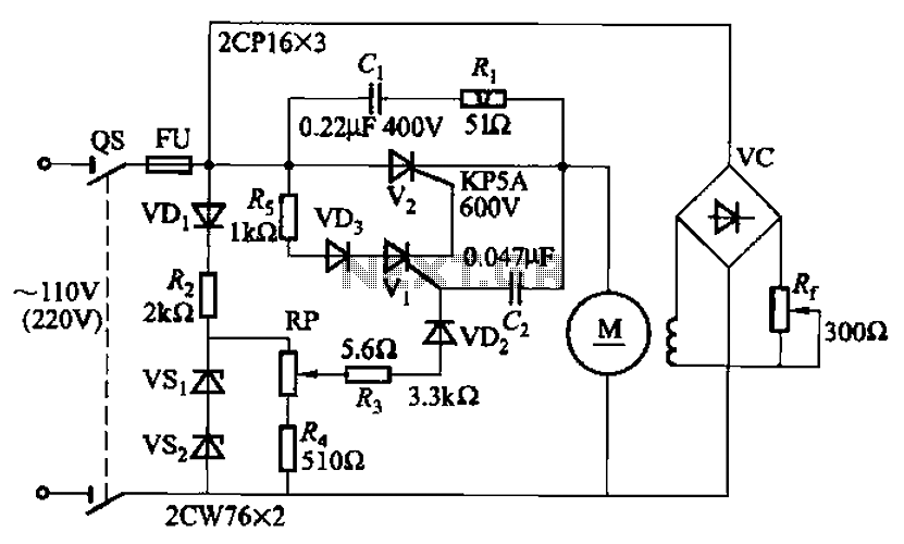
A 100W resistance-triggered motor control circuit designed for arc welding machines. It features an adjustment potentiometer (Rr) that can modify the DC motor excitation current. Additionally, a regulator (RP) is included to adjust the DC motor armature voltage, enabling...
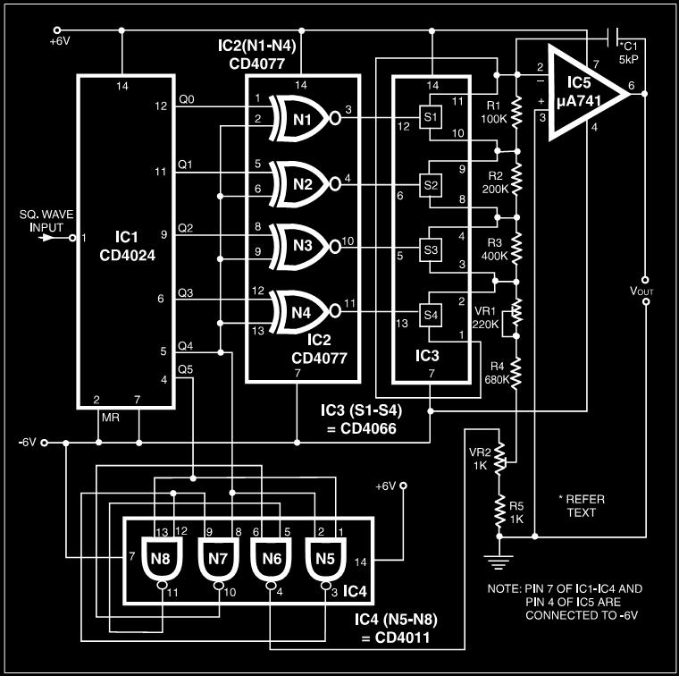
Many electronic devices rely on the shape of signals. Generating square wave signals from sine waves is relatively straightforward, while the reverse process is more challenging. The static square wave-to-sine wave converter circuit can produce an accurate sine wave...
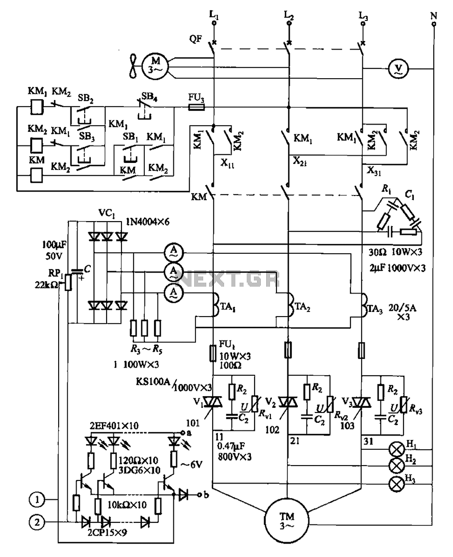
The circuit illustrated in Figure 3-178 is designed for controlling the speed and torque of a motor used in a continuous casting machine. It consists of the main circuit, a trigger circuit, and both manual and automatic control signal...
This amplifier circuit is designed to enhance TV signals in the UHF range. It employs a low-noise transistor, providing an amplification of 10 to 15 dB within the frequency spectrum of 400 MHz to 850 MHz. It is crucial...
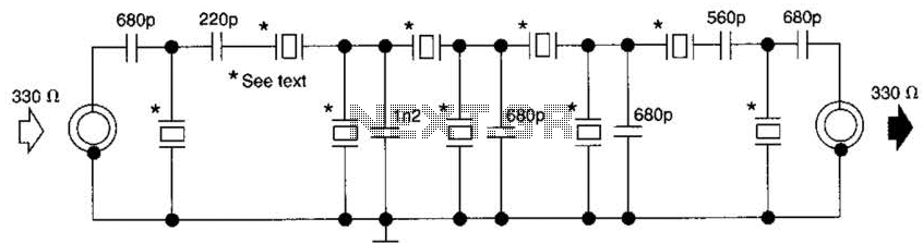
This filter utilizes five 455-kHz ceramic resonators. The impedance is 330 ohms, the bandwidth is 800 Hz, and the ultimate rejection is greater than 60 dB. Additionally, the ceramic resonators can be substituted with crystals. The described filter is a...
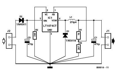
This 3-volt car adapter circuit is based on a standard LT1074CT switching regulator IC. The schematic shows the LT1074CT used as a positive step-down regulator. The 3-volt car adapter circuit employs the LT1074CT, which is a high-efficiency switching regulator capable...