
solar charger schematics

The solar charger circuit operates by converting solar energy into electrical energy, which is then used to charge the specified battery types. The primary components of this circuit include a solar panel, a charge controller, and the battery itself.
The solar panel generates electricity when exposed to sunlight, producing a voltage output that varies with the intensity of the sunlight. This output is typically in the range of 12 to 18 volts, depending on the panel specifications. The charge controller is a critical component that regulates the voltage and current delivered to the battery. It ensures that the battery is charged efficiently without exceeding its voltage limits, which could lead to damage or reduced lifespan.
The circuit features a voltage regulation mechanism that maintains the output voltage within safe limits for the battery being charged. This is achieved through the use of linear regulators or switching regulators, which adjust the voltage according to the battery's state of charge. Additionally, current regulation is implemented to prevent excessive current flow into the battery, which could also lead to overheating or other forms of damage.
An essential safety feature of the circuit is the over-voltage cutoff. This mechanism disconnects the solar panel from the battery when the voltage exceeds a predetermined threshold, thereby protecting the battery from overcharging. This is typically accomplished using a relay or a transistor that is controlled by a voltage sensing circuit.
In summary, this solar charger circuit is an efficient and safe solution for charging Lead Acid or Ni-Cd batteries using renewable solar energy. Its built-in regulation and safety features ensure reliable performance and longevity of the battery being charged, making it suitable for a variety of applications such as powering small electronic devices, garden lights, or backup power systems.Here is a solar charger circuit to charge Lead Acid or Ni-Cd batteries using solar energy. The circuit harvests solar energy to charge a 6 volt 4. 5 Ah rechargeable battery for various applications. The charger has Voltage and Current regulation and Over voltage cut off facilities. 🔗 External reference
Related Circuits
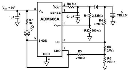
NiMH charger circuit diagram using ADM66A. Related searches include charger circuit, NiMH charger circuit, lead acid battery charger circuit, LiPo charger circuit, automatic battery charger circuit, simple battery charger circuit, lithium battery charger circuit, charger circuit diagram, and 12V...
Schematic of an automatic solar garden light circuit with 10 super bright white LEDs that will automatically activate at night. The automatic solar garden light circuit is designed to harness solar energy for illumination purposes during nighttime. The circuit typically...
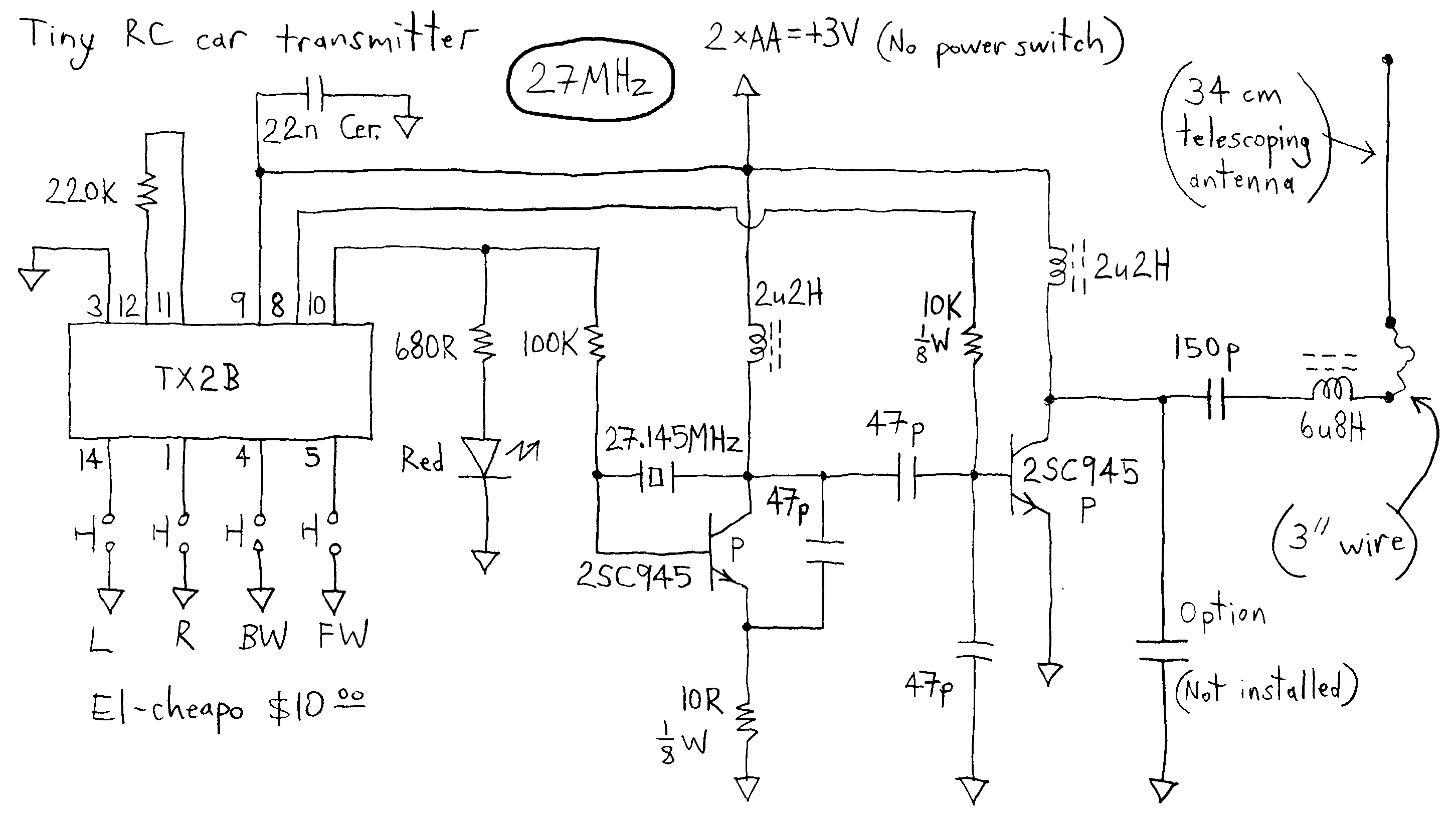
The transmitter runs on only 3V whereas most others run on more voltage. This dirt cheap item uses non-adjustable inductors so it is not possible to tweak for higher output. The common TX2B chip is manufactured by HIGHLAND (SHENZHEN)...
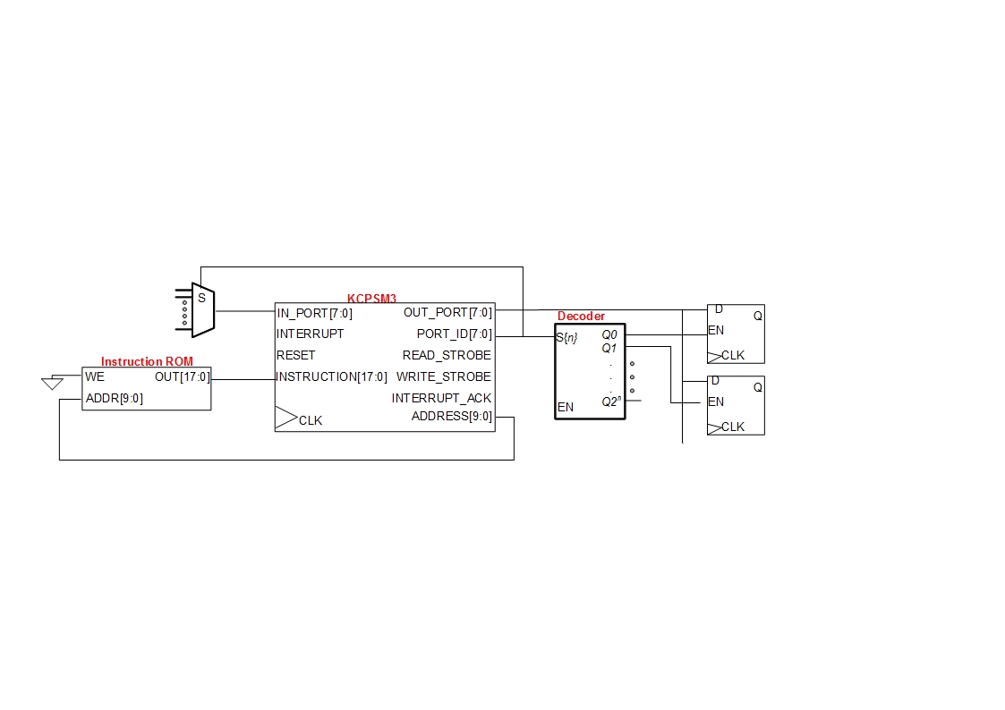
A small digital design utilizes a Xilinx Picoblaze softcore processor. Creating acceptable quality schematics has proven to be frustrating and time-consuming. Previous attempts to integrate existing schematics from LTSpice or Eagle into the documentation yielded unsatisfactory results, appearing fuzzy...
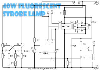
This circuit is designed for a 40 Watt fluorescent lamp. It operates similarly to a traditional strobe light, but utilizes a fluorescent tube instead. The fluorescent tube remains continuously energized, with both electrodes supplied with electricity. This current causes...
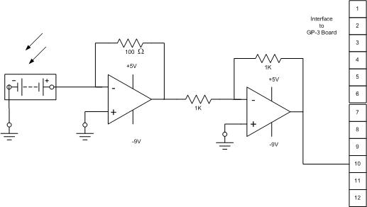
The solar cell used for the solar tracking experiment is made from crystalline silicon, with a maximum voltage rating of 55V and a maximum current rating of 300 mA. It can be purchased at local Radio Shack stores for...