
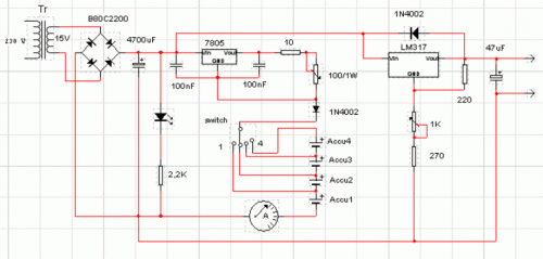
Solar Panel Based Charger And Small LED Lamp

The photovoltaic module operates under the principle of converting solar energy into electrical energy, which is facilitated by the photovoltaic effect. The output voltage of 16.5V is suitable for charging various battery types, making it a versatile power source. The 1N5402 diode not only ensures proper polarity but also prevents backflow of current that could damage the solar panel. The inclusion of an ammeter allows for real-time monitoring of the charging current, which is crucial for maintaining battery health and preventing overcharging.
The circuit design incorporates safety features, such as the reverse polarity protection provided by diode D2, which safeguards against potential damage from incorrect battery connections. The use of a fuse further enhances safety by disconnecting the circuit in case of excessive current flow, thus preventing overheating and potential hazards.
For the lead-acid battery charging method, the design emphasizes the importance of using pulsating DC to facilitate efficient charging. This method helps in reducing sulphation on the battery plates, which can significantly extend the battery's lifespan. The recommendation to switch to a standard pulsating DC charger periodically is a prudent practice to ensure optimal battery maintenance.
The charging circuits for Ni-Cd and Li-ion batteries utilize voltage regulators (IC1 and IC2) to maintain a constant current, essential for safe and effective charging. The choice of specific resistors (R2 and R3) to limit the charging current is critical in preventing damage to the batteries and ensuring their longevity.
The LED-based lamp circuit is designed for simplicity and cost-effectiveness. The parallel connection of LEDs allows for uniform brightness and efficient power distribution. The use of a low-voltage source (3.6V) makes this circuit suitable for battery-powered applications, enhancing its portability and convenience.
Overall, this circuit represents a comprehensive solution for harnessing solar energy for charging various battery types while ensuring safety, efficiency, and ease of use.You can save on your electricity bills by switching to alternative sources of power. The photovoltaic module or solar panel described here is capable of delivering a power of 5 watts. At full sunlight, the solar panel outputs 16. 5V. It can deliver a current of 300-350 mA. Using it you can charge three types of batteries: lead acid, Ni-Cd and Li-io n. The lead-acid batteries are commonly used in emergency lamps and UPS. The working of the circuit is simple. The output of the solar panel is fed via diode 1N5402 (D1), which acts as a polarity guard and protects the solar panel. An ammeter is connected in series between diode D1 and fuse to measure the current flowing during charging of the batteries.
As shown in Fig. 1, we have used an analogue multimeter in 500mA range. Diode D2 is used for protection against reverse polarity in case of wrong connection of the lead-acid battery. When you connect wrong polarity, the fuse will blow up. For charging a lead-acid battery, shift switch S1 to on` position and use connector A. ` After you connect the battery, charging starts from the solar panel via diode D1, multimeter and fuse.
Note that pulsating DC is the best for charging lead-acid batteries. If you use this circuit for charging a lead-acid battery, replace it with a normal pulsating DC charger once a week. Keep checking the water level of the lead-acid battery. Pure DC voltage normally leads to deposition of sulphur on the plates of lead-acid batteries. For charging Ni-Cd cells, shift switches S1 and S3 to on` position and use connector B. ` Regulator IC 7806 (IC1) is wired as a constant-current source and its output is taken from the middle terminal (normally grounded).
Using this circuit, a constant current goes to Ni-Cd cell for charging. A total of four 1. 2V cells are used here. Resistor R2 limits the charging current. For charging Li-ion battery (used in mobile phones), shift switches S1 and S2 to on` position and use connector C. ` Regulator IC 7805 (IC2) provides 5V for charging the Li-ion battery. Using this circuit, you can charge a 3. 6V Li-ion cell very easily. Resistor R3 limits the charging current. Fig. 2 shows the circuit for a small LED-based lamp. It is simple and low-cost. Six 10mm white LEDs (LED2 through LED7) are used here. Just connect them in parallel and drive directly by a 3. 6V DC source. You can use either pencil-type Ni-Cd batteries or rechargeable batteries as the power source. Assemble the circuit on a general-purpose PCB and enclose in a small box. Mount RCA socket on the front panel of the box and wire RCA plug with cable for connecting the battery and LED-based lamp to the charger.
🔗 External reference
Related Circuits
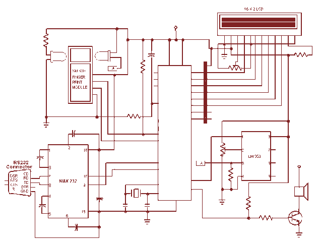
This project gives you a fingerprint based attendance system with 8051 microcontroller. The SM630 fingerprint module is used for fingerprint matching. It can store a max of 768 fingerprints. The admin can add/delete records from the PC through the...
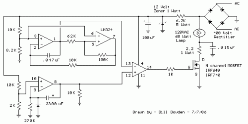
This circuit gradually illuminates a 120VAC lamp over an approximate 20-minute period. A bridge rectifier provides 120V DC to the MOSFET and the 60-watt lamp. A 6.2K, 5-watt resistor and a zener diode are employed to reduce the voltage...
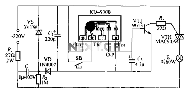
The circuit utilizes a KD-9300 music IC, which activates when the button switch (SB) is pressed, causing the electric lamp (E) to light up for approximately 20 seconds before automatically turning off. The setup includes a half-wave rectifier and...
This circuit can switch two or more devices on and off in response to a series of rapid handclaps. The claps are picked up by an electret microphone. The circuit operates by utilizing an electret microphone, which serves as the...
This circuit serves a function for digital cameras. It is well-known that digital cameras have considerable power consumption. The circuit is designed to optimize power management for digital cameras, addressing the challenge of high energy usage during operation. It...
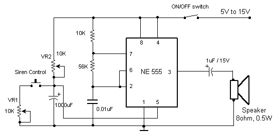
The circuit diagram of an electronic siren based on the NE555 timer produces a sound similar to that of a factory siren. The NE555 timer IC functions as an astable multivibrator with a center frequency of approximately 300 Hz....