
Solarize your backpack and power all your gizmos

The project involves integrating a solar panel with a rechargeable battery system that can be easily detached from a backpack for convenience. The solar panel captures sunlight and converts it into electrical energy, which is then used to charge the battery. The battery can store energy for later use, allowing users to charge their gadgets on-the-go.
Key components of the circuit include a solar panel, a charge controller, a rechargeable battery (such as a lithium-ion or lead-acid battery), and output connectors for various devices. The solar panel should be selected based on the desired power output and size constraints of the backpack. A charge controller is essential to manage the charging process, preventing overcharging and ensuring the longevity of the battery.
Wiring connections must be made carefully to ensure proper functionality. The solar panel's positive and negative terminals should connect to the input of the charge controller, while the output of the charge controller connects to the battery. Additionally, output terminals should be provided for charging devices, with appropriate connectors such as USB ports for compatibility with common gadgets.
This system may also include features such as a voltage regulator to maintain consistent output voltage and LED indicators to show charging status. The overall design should prioritize lightweight materials and compactness to ensure it remains portable and practical for backpack use. Proper insulation and weatherproofing may also be necessary to protect the electronic components from environmental factors.In this instructable I`ll show you how to build a detachable solar panel and battery charger for your backpack. This can power or charge all your gadg.. 🔗 External reference
Related Circuits
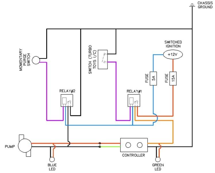
Coolingmist Stage 3 HOM Trunkmount kit installation is underway to enable continuous enjoyment of the HOM system. The setup includes a switch for arming the system and a separate push-button for purging. The intercooler sprayer assembly will be removed...
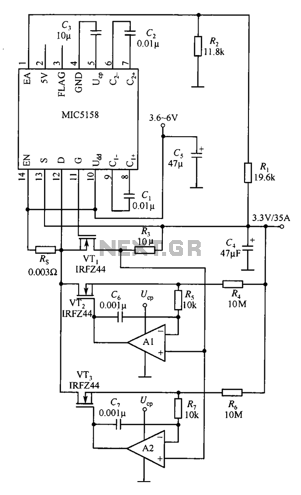
The MIC5158 is designed to manage tasks by controlling multiple external N-channel MOSFETs in parallel, which enables high current or high power output for a linear regulator circuit. This is illustrated in the accompanying figure. The operational amplifier circuit...
Unless a custom-made transformer is available, the circuit design is constrained by the transformer that is accessible. If the primary winding is not center-tapped, the design is limited to an AB driver. A center-tapped primary winding allows for the...
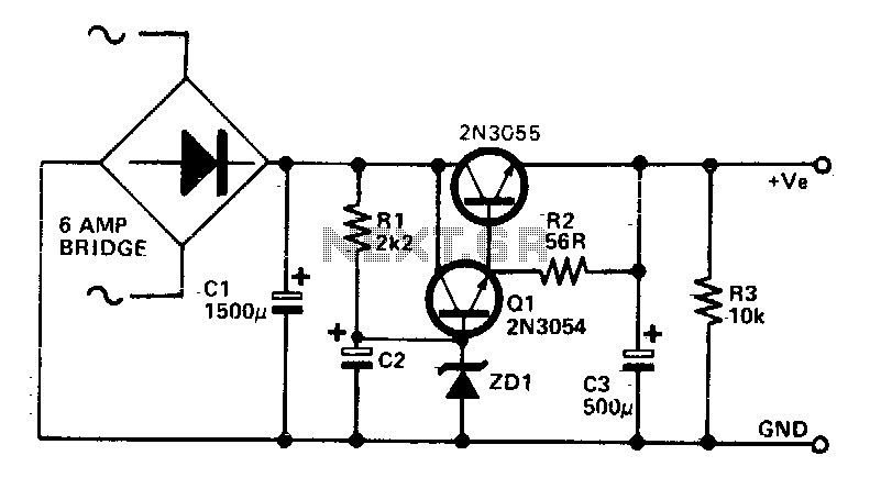
This circuit can be utilized in applications requiring high current with low ripple voltage, such as in high-powered Class AB amplifiers where high-quality audio reproduction is essential. Q1, Q2, and R2 can be considered as a power Darlington transistor...
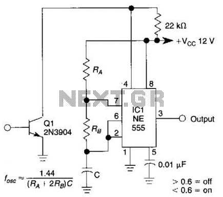
This gated 1-kHz oscillator provides press-to-turn-off functionality, along with waveforms available at the output of pin 3 and across capacitor C1. The gated 1-kHz oscillator circuit is designed to generate a square wave output at a frequency of 1 kHz....
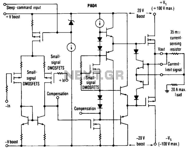
This circuit from Apex Microtechnology can deliver 180 V peak-to-peak at 90 kHz into a 4-ohm load. The PA04 can deliver 400 watts RMS into an 8-ohm load with low total harmonic distortion at frequencies exceeding 20 kHz. The circuit...