
Solid State Free energy Basic

This circuit operates on the principle of energy storage and transfer using capacitors and a DC-DC converter. The primary component, the capacitor, is charged to a certain voltage level and is capable of storing electrical energy. When the circuit is activated, the stored energy in the capacitor is used to power a connected load, which could be any device that requires electrical energy to operate.
Once the capacitor discharges to approximately half of its capacity, it is then connected to a DC-DC converter. The function of the DC-DC converter is to step up or step down the voltage as necessary, allowing for efficient energy transfer back to the capacitor. This converter is crucial as it enables the recharging of the initial capacitor from the energy that remains after powering the load.
The process is cyclical; after the capacitor is recharged, it can once again supply power to the load. This design not only allows for repeated use of the stored energy but also ensures that there is a surplus of energy available after each cycle, enhancing the efficiency of the entire system.
Key considerations in the design of this circuit include selecting appropriate capacitor values to ensure that they can handle the load requirements, choosing a suitable DC-DC converter that matches the voltage and current ratings, and implementing control mechanisms to manage the charging and discharging cycles effectively. Additionally, protection circuits may be necessary to prevent over-voltage or over-current conditions that could damage the components.
Overall, this circuit exemplifies an efficient energy management system that leverages capacitors and DC-DC conversion technology to optimize energy usage and enhance the performance of electronic devices.A circuit that uses the capacitors to run the load and then by discharging the 1/2 full capacitor into a DC-DC converter we can recharge the initial cap and start again. And have some energy left over. 🔗 External reference
Related Circuits
Instructions for supervising landscaping projects recommended by satellite relay protection and automatic safety devices. This includes information on the general table for three remote programs related to petrochemical engineering construction, electrical transmission, and the intelligent implementation of community weak...
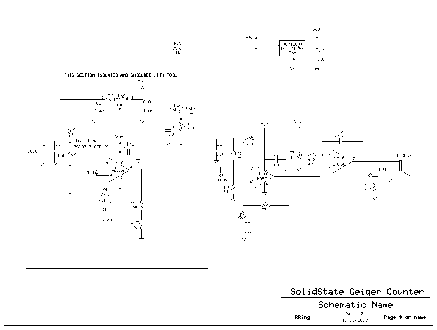
Photodiodes convert light into current, and this current can be converted into voltage and amplified. While this process seems straightforward, designing a photodiode detector for gamma photon detection is more complex. Although the circuit is not particularly complicated, the...
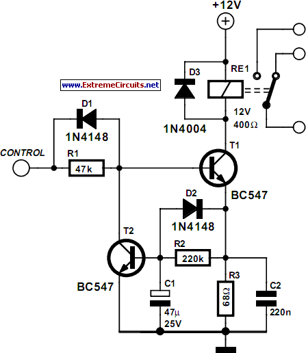
Some relays may become warm if they remain energized for an extended period. The circuit presented here will actuate the relay as before but will reduce the hold current through the relay coil by approximately 50%, significantly decreasing heat...
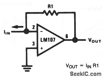
This basic circuit feeds the input current directly into the summing node (pin 2), causing the op-amp output to adjust and extract the same current from the summing node through resistor R1. The scale factor of the circuit is...

Tesla radiant energy collectors and methods for creating these devices have been explored. Various designs have been developed, including the use of a standard rectification bridge for antenna and ground, a Greinacher voltage quadrupler rectifier, and experimentation with different...
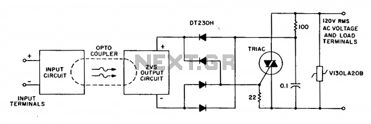
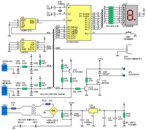
A complete zero-voltage switch solid-state relay consists of an input circuit, an output circuit, and a power thyristor. The circuit features a triac power thyristor with a snubber circuit and GE-MOVRII Vans for transient over-voltage protection. A 22-ohm resistor...