
Solid State Relay

The Solid State Relay (SSR) Switch described is designed for efficient control of high-power circuits using low-power signals. The primary function of this relay is to provide electrical isolation between the control circuit and the high-power load, ensuring safe operation and protecting sensitive components from high voltages.
This SSR operates within a voltage range of 24 to 240 VAC, capable of handling loads up to 500 watts. The triggering mechanism requires a control voltage of 2 to 5 VDC, which corresponds to TTL (Transistor-Transistor Logic) levels, allowing it to interface easily with microcontrollers and other low-power devices. The input current requirement for triggering is 10 mA, making it suitable for interfacing with various control systems without excessive power consumption.
An optocoupler is integrated into the design to ensure electrical isolation between the input and output, enhancing safety and reliability. The use of an optocoupler prevents high voltage from affecting the control side of the circuit, which is critical in applications where sensitive electronics are involved.
The relay features a Power Battery Terminal (PBT) for straightforward connection to the 230 VAC mains supply, facilitating the installation process. Additionally, terminal pins are provided for connecting the input trigger signal, allowing for flexible wiring options based on the specific application requirements.
Heat dissipation is managed through the inclusion of a heatsink for the TRIAC, which is the primary switching component in this SSR. The heatsink is essential for maintaining optimal operating temperatures, thereby prolonging the life of the relay and ensuring consistent performance under load.
For mounting convenience, the PCB is designed with four mounting holes, each measuring 3.2 mm. This allows for secure installation in various enclosures or on mounting surfaces. The dimensions of the PCB are compact, measuring 29 mm by 74 mm, making it suitable for applications with space constraints.
Overall, this Solid State Relay Switch kit is an effective solution for controlling high-power devices with low-power signals, combining safety, efficiency, and ease of use in its design.Solid State Relay Switch is a simple kit which will help you control (ON / OFF) a single high power circuit from a low power drive. Load - 24 to 240 VAC @ 500 W. Trigger voltage - 2 to 5 VDC (TTL) @ 10 mA. Input isolated with use of Optocoupler. Power Battery Terminal (PBT) for easy input 230 VAC mains and load connection. Terminal pins for connecting input trigger signal. Heatsink for TRIAC. Four mounting holes of 3.2 mm each. PCB dimensions 29 mm x 74 mm 🔗 External reference
Related Circuits
The transformer is a 220V to 12V, 50Hz, and 3.6VA PCB type transformer. The model depicted is HRDiemen E3814056. Being encapsulated, it is isolated from external influences. A 250V 400mA glass fuse protects the circuit from damage caused by...
This circuit is similar to the previous one but incorporates a photoresistor to trigger the flip-flop instead of a push button. A bias resistor is placed in series with the photoresistor to ensure that adequate voltage is present at...
This circuit provides a visual 9-second delay using 10 LEDs before closing a 12-volt relay. When the reset switch is closed, the 4017 decade counter is reset to the 0 count, illuminating the LED driven from pin 3. The...
The circuit requires a double pole, double throw relay in conjunction with a single transistor to allow toggling the relay with a momentary push button. One set of relay contacts is used to control the load, while the other...
Control a latching relay that requires approximately 70-90mA, while the Raspberry Pi can supply only about 40mA. A relay suitable for managing home appliances is needed, which can also be operated by the Raspberry Pi. To achieve control over a...
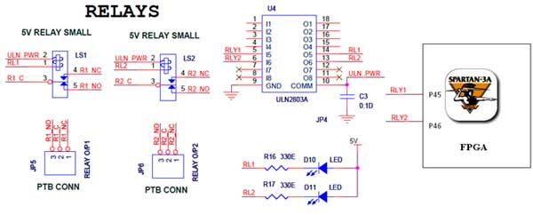
The Spartan-3an board features external 5V relay interfacing, as illustrated in the accompanying figure. The ULN2803 acts as a driver for the FPGA I/O lines, with the driver's outputs connected to the relay modules. A PTB connector is available...