
Solid state relay circuit with MOC3011 triac driver

The solid-state relay (SSR) circuit is designed to control high-voltage loads with low-voltage control signals, ensuring electrical isolation between the control and load circuits. The MOC3011 triac driver serves as an essential component in this configuration, facilitating the switching action of the relay while providing input protection.
The circuit operates by receiving a control signal within the specified input voltage range of 3 to 30 volts DC. Upon activation, the MOC3011 triggers the triac, allowing current to flow through the load circuit. This configuration eliminates the need for mechanical contacts, thereby enhancing reliability and longevity.
Input protection is critical in SSR applications to prevent damage from voltage spikes or transients. The circuit may incorporate additional protective elements such as diodes or transient voltage suppressors to safeguard the MOC3011 and the relay from overvoltage conditions.
The output side of the solid-state relay can handle higher voltages and currents, making it suitable for various applications, including industrial automation, lighting control, and motor control. The design ensures that the relay can handle inductive loads, which may generate back EMF during switching, potentially damaging sensitive components.
Overall, the solid-state relay circuit with the MOC3011 triac driver and input protection provides a robust solution for controlling high-power devices with low-voltage control signals while mitigating the risks associated with electrical transients.Solid-state relay circuit with input protection of the MOC3011 triac driver. The input voltage to the protection circuit can be 3 to 30 volts DC (courtesy Motorola Semiconductor Products Inc. ). 🔗 External reference
Related Circuits
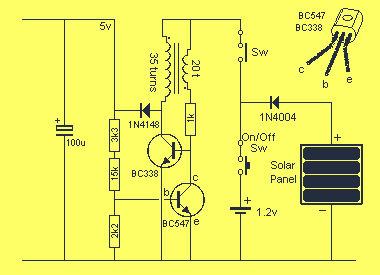
This project uses the 1.2v rechargeable battery and solar panel from a Solar Garden Light. These lights can be bought for less than $5.00 in most $2.00 shops or similar shops that sell general household items. We are also...

The circuit on this page is for a simple light detector circuit board that has 8 detectors that can be used with visible or infrared light systems. The detectors use LM339 voltage comparators as the active element. Phototransistors or...
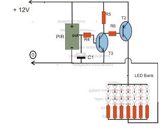
The circuit is an LED driver that responds to ambient light as well as the presence of an intruder, varying its illumination accordingly. Additionally, it includes an ambient light sensor to turn the LEDs on and off, and a...

The circuit illustrated in Figure 3-145 employs a rectifier diode brake for neutral grounding in a three-phase, four-wire power supply system. This circuit design incorporates a rectifier diode brake, which plays a crucial role in ensuring the safety and reliability of...

This oscillator is a variation of the oscillator presented by Ulrich L. Rohde, DJ2LR, in his article "Evaluating Noise Sideband Performance in Oscillators," published in Ham Radio, October 1978, Page 51. The original circuit can be found at the...

An AC-DC power supply without a power switching circuit is typically employed in lighting load circuits. When the power grid is restored, the standby power supply automatically switches on. The automatic switching circuit utilizes a transistor, as illustrated. The...