
Sound AC switch

The described circuit effectively combines sound detection with voltage amplification to control power delivery through the use of semiconductor devices. The 741 op-amp operates as an inverting amplifier, where the input signal from the speaker is inverted and amplified based on the gain set by the feedback resistor R3. The use of a 1-megohm potentiometer for R3 allows for fine-tuning of the amplifier's gain, making it adaptable to various sound levels and environments.
The operational amplifier's output is connected to the gate of SCR1, which serves as a switch that can be turned on by the amplified signal. The SCR is a controlled rectifier that can conduct current in one direction when triggered, and it remains in the conducting state until the current flowing through it drops below a certain threshold. This characteristic makes it suitable for applications where the circuit needs to maintain its state until a manual reset is performed.
The Triac, TR1, is used to control the load, providing the necessary voltage once SCR1 is activated. The Triac can handle alternating current loads, making it ideal for applications requiring control over AC devices. The combination of SCR1 and TR1 ensures that once the sound is detected and the circuit is activated, the load remains powered until the switch is reset, allowing for a reliable sound-activated control mechanism.
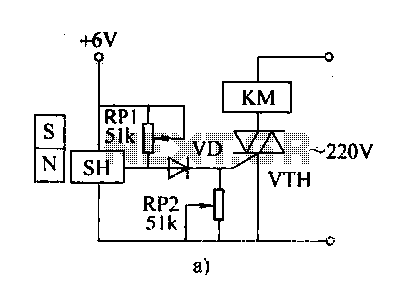
Overall, this circuit design demonstrates a practical application of operational amplifiers, SCRs, and Triacs in creating a sound-activated system capable of controlling electrical loads based on acoustic signals. The careful selection of components and their configuration plays a critical role in determining the performance and sensitivity of the sound detection and amplification system.The circuit uses a 741 op amp operating as an inverting amplifier to amplify the voltage produced by an 8-ohm speaker used to detect any sounds. The feedback resistor R3, a 1-megohm potentiometer used to vary the gain of the amplifier determines the sensitivity of the circuit.
When Si is closed in the (SET)-position and a sound is applied to the speaker, SCR1 is turned on. It will remain in conduction until the anode voltage is removed by opening SI, putting it in its RESET position. (Once an SCR is turned on, the gate or trigger has no control over the circuit.) As long as the SCR conducts, the Triac, TR1, will remain on and supply voltage to the load.
Related Circuits
The 555 circuit can be re-triggered if the input is held low for a duration longer than the output pulse. To prevent this from occurring, an additional timing circuit has been incorporated, consisting of a 1 Megohm resistor and...
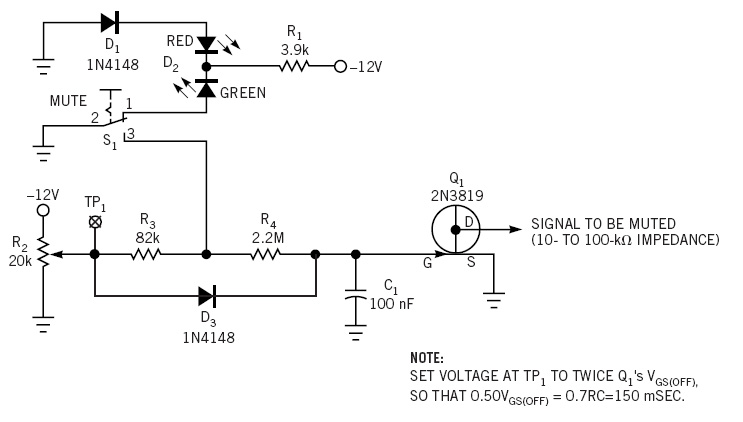
This simple circuit is a line-level audio signal muting switch based on a soft-action power on/off process. When the S1 switch is closed, R4, C1, and Q4 JFET are activated to mute the audio signal. The circuit operates by utilizing...
Described here is a very inexpensive solution to many phono-controlled applications like remote switching on, for instance, or activating a camera, tape recorder, burglar alarms, toys, etc. The circuit given here employs a condenser microphone as the pick-up. A...
The automatic weapon features a magnetic switch circuit that is simple, reliable, has a low failure rate, and offers good versatility. It can be used for output performance or converted into mechanical displacement applications. The circuit diagram utilizes a...

At a predetermined level of declining terminal voltage, the circuit disconnects the battery from the load and halts potentially destructive battery discharge. Q1, a high-side, floating-source MOSFET, acts as the switch. The overall circuit draws about 500 µA when...
Information is needed regarding a circuit to manage the Remote Coax Ameritron RCS-10, as no diagram can be found on Google. The Ameritron RCS-10 is a remote coax switch designed for amateur radio applications, allowing users to control multiple antennas...