
Sound-Activated Lamp (Relay Switch)
")
The circuit utilizes a sound sensor, which is typically a microphone or a piezoelectric sensor, to detect sound waves. Upon detecting a sound above a predetermined threshold, the sensor generates an output signal. This output signal is then used to trigger a transistor or a relay, which serves as the switch in the circuit.
In detail, the sound sensor is connected to an amplifier circuit to ensure that even low-level sounds can be detected. The amplified signal is then fed into a comparator circuit that compares the sensor output with a reference voltage. When the sound level exceeds the reference, the comparator output goes high, activating the transistor or relay.
The transistor acts as a low-side switch, controlling the power to a load, which could be a light, motor, or any other electronic device. If a relay is used, the sound detection can control larger loads that require higher voltage or current than the transistor can handle.
Power supply considerations are also essential; typically, a battery or a regulated power supply is used to ensure consistent operation. Additionally, capacitors may be included in the circuit to filter noise and stabilize the voltage levels.
This sound-activated switch circuit is versatile and can be adapted for various applications, including automatic light control, sound-activated alarms, or even as a trigger for more complex systems in robotics or home automation.This simple circuit shown int the schematic diagram actives the switch using sound. We can use this circuit for various applications, such as automatic (s.. 🔗 External reference
Related Circuits

This discussion focuses on headlamp dimmer-controlled fog lamps within the Ford Raptor Lighting Modifications Forum, part of the Ford Raptor Forums - Modifications category. For those interested in installing fog lamps that can be controlled by the dimmer switch...

The following circuit illustrates the Bedside Lamp Timer Circuit utilizing the CD4060 integrated circuit (IC). It operates for 30 minutes, with a blinking LED indicating the last 6 minutes of operation. The Bedside Lamp Timer Circuit is designed to provide...
This ultra-bright white LED lamp operates on 230V AC with low power consumption. It is suitable for illuminating VU meters, SWR meters, and similar applications. The cost of ultra-bright LEDs available in the market ranges from Rs 8 to...

Several individuals have struggled to locate the transformer necessary for the Black Light project. Consequently, an investigation was conducted to identify a fluorescent lamp driver that does not necessitate any specialized components. A suitable option was discovered in Electronics...

It connects to the USB port and is ideal for checking motherboard switches and jumper settings. Many users may recall a commercial product from a few years ago, the "Itty Bitty Book Light," which was designed to clip onto...
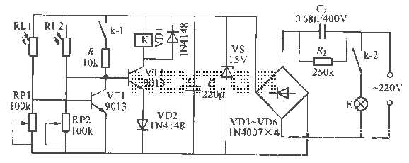
This is a remote-controlled light switch circuit that can be used for remote control toys, flashlight operation, or laser pointers. When the light from a torch illuminates the photosensitive resistor RL2, its resistance decreases, causing transistor VT2 to turn...