
Sound-activated switch

The circuit described involves a signal detection mechanism that utilizes a silicon-controlled rectifier (SCR) to control the illumination of lamp II based on the amplitude of the input signal. The threshold for triggering the SCR is set at approximately 0.7 volts, which is determined by the resistor Rl. When the input signal, which is derived from an audio source such as a microphone, exceeds this threshold, the SCR is activated, allowing current to flow and thus lighting lamp II.
The audio signal from the microphone is first processed by transistor Q1, which functions as an amplifier. The purpose of Q1 is to increase the amplitude of the audio signal to a level suitable for further processing. This amplification stage is crucial, as it ensures that even low-level audio signals can effectively trigger the SCR when they reach the required voltage threshold.
The design may include additional components, such as capacitors for AC coupling and filtering, which help to stabilize the signal and prevent noise from affecting the performance of the circuit. The use of Rl is also significant, as it not only sets the trigger level for the SCR but may also influence the response time of the circuit, determining how quickly the lamp can turn on or off in response to signal changes.
Overall, this circuit exemplifies a simple yet effective method for controlling a load (lamp II) based on the amplitude of an audio signal, utilizing basic electronic components to achieve the desired functionality. Peaks of signal (adjusted by Rl) greater than about 0.7 volts trigger the SCR and light lamp II. The audio from Mic is amplified by Ql.
Related Circuits
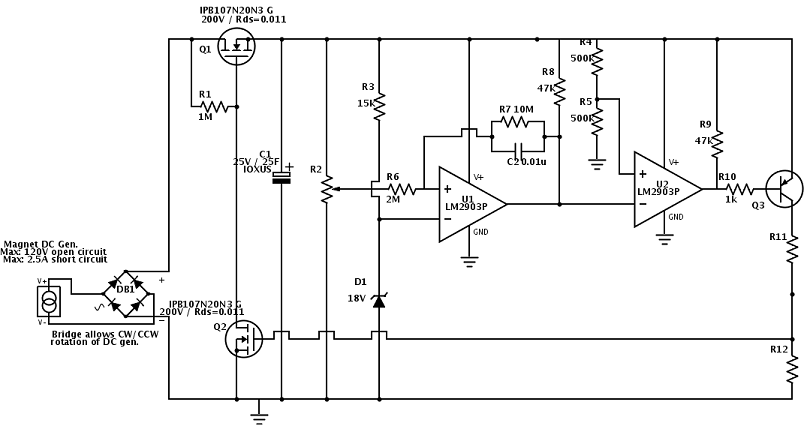
A flywheel-driven permanent magnet DC generator is used to charge a bank of supercapacitors rated at 35 farads and 25V. The maximum charge voltage is limited to 22V using a comparator and a zener reference due to the absence...
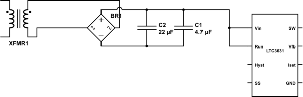
The leads from the transformer to the circuit are quite long (>5m). The 110V side of the transformer has been switched off frequently, which likely caused a spike on the secondary (24V) side. The input pin of the LTC3631...
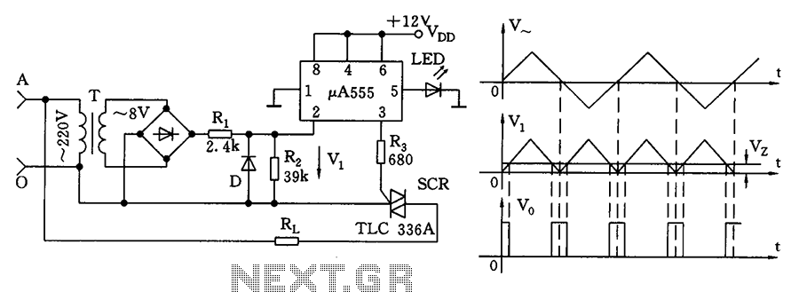
The zero volt switching circuit generates a trigger pulse at the zero crossing of the AC voltage. To facilitate this, the zero crossing of the 555 limit comparator is connected to a single form, with the comparison voltage set...
This is a simple circuit that does the day/night switchings you have in mind. POT1 is used to set the light level at which the circuit switches from enable to disable. The described circuit functions as an automatic day/night switch,...

By incorporating discrete inductors in series with the device, it is possible to "tune out" some of the capacitance and enhance the eye opening. By adding sufficient inductance to peak the third harmonic at 240 MHz, while considering the...
The timing circuit utilizes an electronic switch composed of F1, F2, and VT1 to reduce quiescent current to approximately 1 to 2 A with the 555 timer. Upon initial power-up, the voltage across capacitor C2 cannot instantly change, causing...