
Simple Day/Night switch (40106B)
")
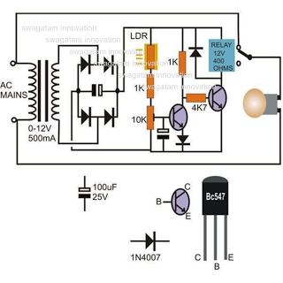
The described circuit functions as an automatic day/night switch, utilizing a photoresistor or light-dependent resistor (LDR) in conjunction with a potentiometer (POT1) to control the switching mechanism based on ambient light levels. The circuit typically includes a comparator, which compares the voltage across the LDR with a reference voltage set by the potentiometer.
When the ambient light level falls below the threshold set by POT1, the comparator output changes state, triggering a relay or a transistor to switch on connected loads, such as outdoor lights or other devices. Conversely, as the light level rises above the threshold, the output state changes again, turning off the load.
The circuit may also incorporate additional components such as capacitors for noise filtering and resistors to limit current through the LDR and ensure stable operation. The design should ensure that the LDR is shielded from direct light sources to prevent false triggering during transient conditions.
For practical implementation, it is essential to choose the appropriate values for the resistors and the potentiometer to achieve the desired sensitivity and response time. Testing under various lighting conditions will help fine-tune the circuit for optimal performance. This circuit is suitable for applications in outdoor lighting systems, garden lights, or any scenario where automatic control based on light levels is beneficial.This is a simple circuit that does the day/night switchings you have in mind. POT1 is used to set the light level at which the circuit switches from enable to disable. 🔗 External reference
Related Circuits

Designing a power supply that meets the requirements of Power over Ethernet (PoE) and Voice over Internet Protocol (VoIP) applications can be complex. The low-component-count power supply illustrated in the figure complies with these specifications without requiring intricate circuitry....
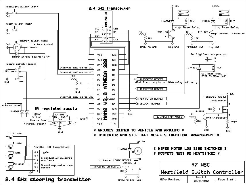
The core of the switch controller is an Arduino Nano microcontroller, which will serve as the interface between the dashboard switches, wireless steering wheel buttons, and the vehicle's lighting, indicators, windscreen wipers, and DigiDash2 GPS stopwatch. This setup facilitates...
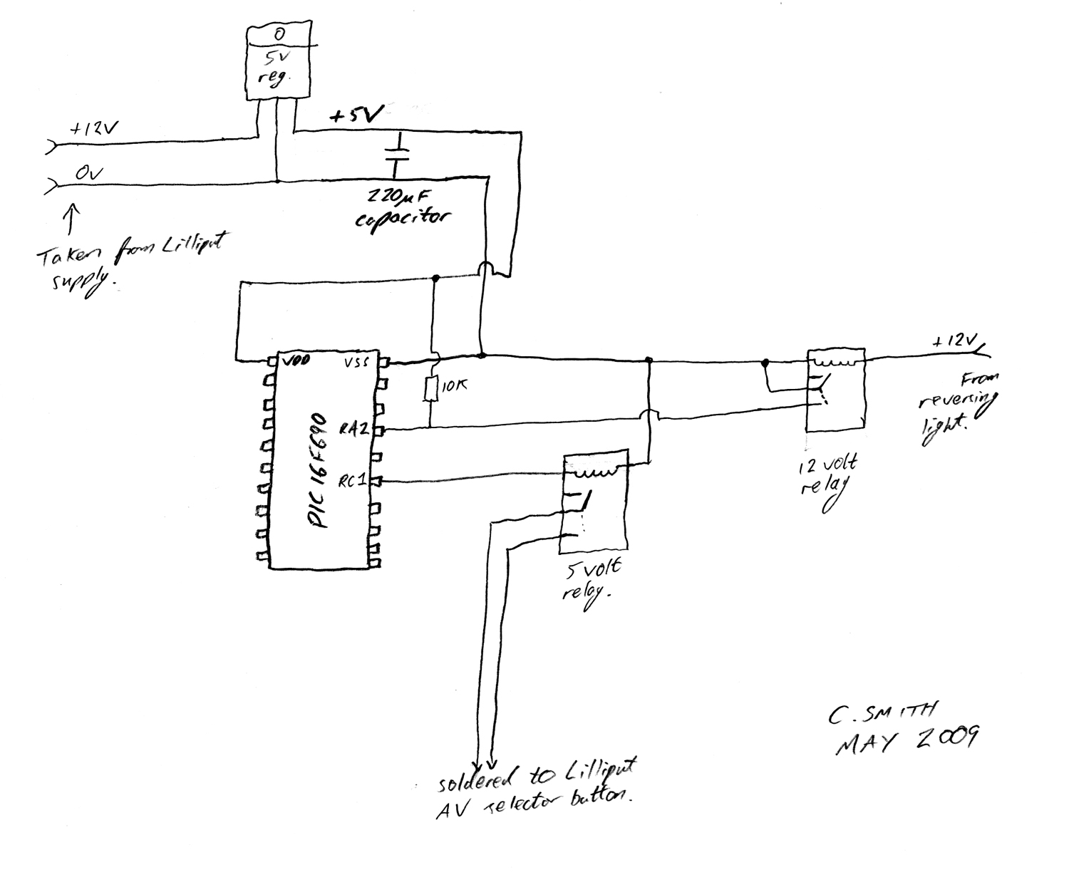
There have been numerous discussions regarding the Lilliput's inability to automatically switch, despite the presence of this feature in the secret menu. The Lilliput display is a versatile device often used in various applications, including professional video production and...
This circuit diagram illustrates a light-activated switch utilizing the National Semiconductor comparator IC LM311 and a light-dependent resistor (LDR). The configuration is based on a voltage comparator circuit centered around IC1. The non-inverting input of IC1 receives a reference...
While conducting background research on the Philips I2C bus, an application note authored by Herman Schutte from Philips Semiconductors Systems Laboratory in Eindhoven was discovered. Mr. Schutte detailed an efficient method for interfacing sections of the I2C bus operating...
The silicon controlled rectifier (SCR), commonly referred to as a thyristor, functions similarly to a diode. When the cathode is negative relative to the anode, current can flow. The silicon controlled rectifier (SCR) is a semiconductor device that plays a...