
Sound-Activated Switch

This circuit is designed to operate in two distinct modes: latched switching and timed switching, providing flexibility for various applications. The audio input from a microphone is amplified by operational amplifiers U1A and U1B, ensuring that the signal is sufficiently strong for further processing.
The core of the timing functionality is implemented using U2, a retriggerable monostable multivibrator, which allows the circuit to generate a pulse of a specified duration upon receiving a trigger signal. The timing characteristics are adjustable through resistors R13 and R14, which set the delay interval between 6 to 60 seconds after the audio signal has ceased. This feature is particularly useful in applications where a delayed action is required post-signal detection.
Switches S1A and S1B serve as selectors, enabling the user to choose between the flip-flop configuration provided by U3 or the timing functionality of U2. This selection capability allows for the circuit's operation to be tailored to specific requirements, whether for maintaining a state until reset (latched mode) or for executing a timed response (timed mode).
Power supply requirements are met by BR1, U5, and their associated components, which convert the input voltage to the necessary levels for circuit operation. An alternative configuration using four silicon diode rectifiers arranged as a bridge can replace BR1, provided that the diodes are rated for at least 50V and 1A to ensure reliability under load conditions.
The output stage of the circuit is driven by transistor Q1, which activates optocoupler U4. This optocoupler provides electrical isolation and allows for safe interfacing with higher voltage components, such as triac TR1, which is responsible for controlling AC loads. This design ensures that the circuit can operate safely and effectively in controlling various devices based on audio input, making it suitable for applications in automation, security, and smart home systems. This circuit provides either latched switching or timed switching. U1A and UlB provide audio amplification from the microphone. U2 is a retriggerable monostable multivibrator. SI A and SIB select either U3, a flip-flop, or U2. R13 and R14 allow a 6- to 60-second timer delay after the sound ceases, in the timed mode. BR1, U5, and associated components form a power supply. Ql drives optocoupler U4 and triggers triac TRl. -If desired, four silicon diode rectifiers connected as a bridge can be substituted for BR1. Just make certain the diodes are rated at least 50V, 1A.
Related Circuits
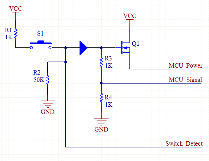
An explanation of how the circuit operates. The TPS_EN line is initially low, as it is connected to a 10k pull-down resistor (not shown in the schematic). When the user presses switch S2, the MOSFET Q2 is activated because...
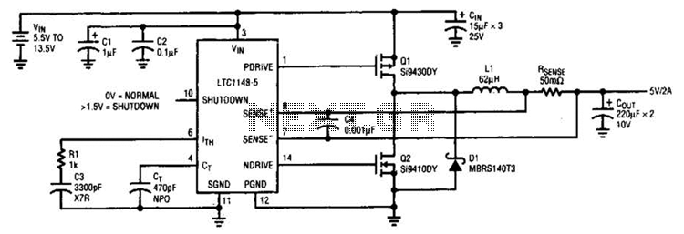
A typical LTC 1148 surface-mount application provides 5 V at 2 A from an input voltage range of 5.5 V to 13.5 V. The operating efficiency, illustrated in B, peaks at 97% and remains above 90% from 10 mA...
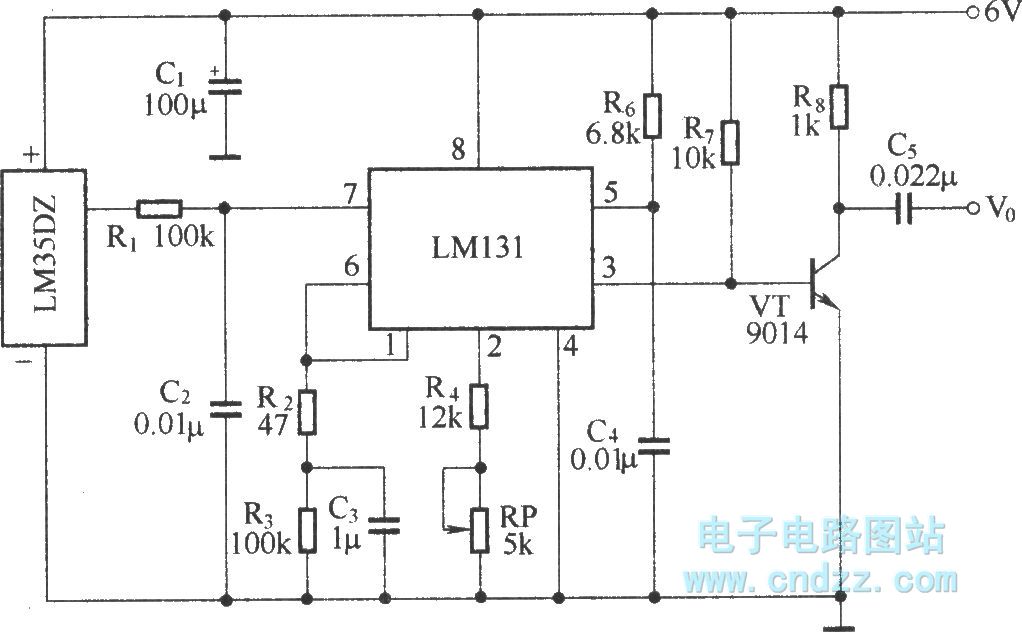
The circuit depicted in the figure integrates a temperature detection system, a temperature-voltage switch, and a voltage-frequency switch to enable remote temperature monitoring. This circuit is connected to a wireless transmission circuit, creating a remote control temperature detection system....
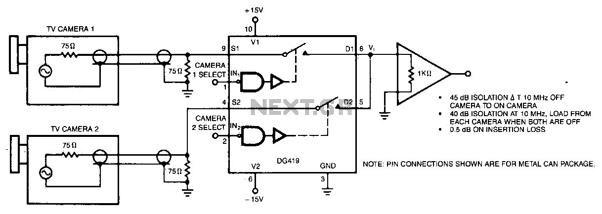
The circuit presented offers 40 dB of isolation at a frequency of 6 MHz and is suitable for general-purpose video switching. The circuit is designed to achieve a high level of isolation, specifically 40 dB, which is critical in applications...
This page outlines the hardware and software design of a printer power switch that is controlled via USB from a Linksys NSLU2, also referred to as Slug. Although primarily designed for printer control, the unit can manage any device...
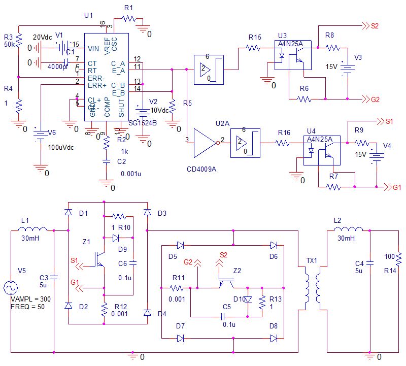
Phase-controlled AC voltage regulator using back-to-back SCRs and diodes, inverse parallel SCRs, and diode-bridge with a single SCR. Input and output voltage waveforms are provided for an input of 250V and an output of 300V. V1 (V5) represents the...