
sound detector tone decoder

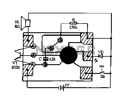
The described circuit functions as a frequency-sensitive triggering mechanism, specifically designed to activate in response to a 1 kHz audio tone. The fundamental operation likely involves a combination of resistors and capacitors configured in an RC timing circuit, which determines the frequency of oscillation.
To modify the frequency of the circuit, it is essential to adjust the values of the resistors and capacitors according to a predefined table, which presumably outlines the necessary component values for various target frequencies. The choice of resistors with a tolerance of 5% or 10% and a power rating of 1/4 watt ensures that the circuit maintains a reliable performance under typical operating conditions. Similarly, the capacitors are specified with a tolerance of 10% and a voltage rating of at least 35 volts, which provides adequate headroom for voltage fluctuations and ensures the longevity of the components.
The circuit may include additional features such as a comparator or a microcontroller to process the incoming tone and provide a digital output or trigger an external device. This could be beneficial in applications where precise tone detection is required, such as in alarm systems, audio processing, or communication devices.
For practical implementation, it is advisable to use a breadboard for initial testing, allowing for easy adjustments of component values to achieve the desired frequency response. Once the circuit is finalized, a PCB design can be created to ensure a compact and robust deployment in a final product. Proper layout considerations should be taken to minimize noise and interference, particularly in environments with other electronic devices.This circuit is designed to trigger on a 1 khz tone. to change this frequency - refer to the table below, then change the resistor and capacitor values accordingly. all resistors are 5 or 10 percent tolerance, 1/4-watt all capacitors are 10 percent tolerance, rated 35 volts or higher 🔗 External reference
Related Circuits
The circuit is fundamentally based on a well-tested simple microphone preamplifier design. A prototype of this circuit has been constructed and has demonstrated effective performance. The Sound Blaster soundcard series (SB16, SB32, AWE32, and AWE64) features a microphone input...
Constantly changing light and sound analog controller circuit 02 The circuit described is an analog controller designed to modulate light and sound in a dynamic manner. It typically utilizes components such as operational amplifiers, resistors, capacitors, and transistors to achieve...
Based on the classic Baxendall tone control circuit, this provides a maximum cut and boost of around 10dB at 10K and 50Hz. As the controls are passive, the last transistor provides a slight boost. The output is designed to...
This circuit gives out an alarm when its sensor is wetted by water. A 555 astable multivibrator is used here which gives a tone of about 1kHz upon detecting water. The sensor when wetted by water completes the circuit...
This portable, pocket-sized mobile transmission detector can detect the presence of an activated mobile phone from a distance of one and a half meters. The mobile transmission detector is designed for convenience and portability, making it an ideal tool for various...
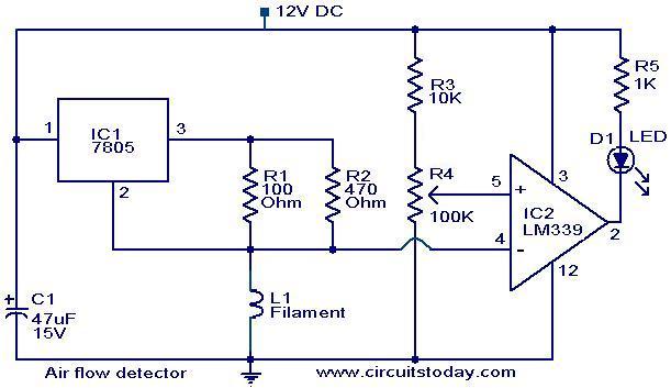
The filament of an incandescent bulb serves as the sensing component of the circuit. When there is no airflow, the resistance of the filament is low. In contrast, when airflow is present, the resistance decreases because the moving air...