
Sound Blaster Microphone Preamplifier

The circuit design includes the following components:
- R1: 1 kΩ resistor
- R2: 220 kΩ resistor
- R3: 4.7 kΩ resistor
- C1: 15 µF, 10V electrolytic capacitor (substitutes of 10 µF or 22 µF can be used if 15 µF is unavailable)
- C2: 22 µF, 10V electrolytic capacitor
- C3: 47 µF, 10V electrolytic capacitor
- Q1: BC547B transistor
The arrangement of these components is crucial for achieving the desired amplification and ensuring compatibility with the Sound Blaster microphone input. The resistors set the biasing and gain levels, while the capacitors handle coupling and decoupling, stabilizing the circuit performance. The BC547B transistor serves as the primary amplification element, and its characteristics will influence the overall gain and noise performance of the circuit. Proper layout and soldering techniques should be employed to minimize noise and interference, ensuring optimal operation of the microphone preamplifier circuit.Circuit is based basically on quite well tested my simple microphone preamplifier. I have built one prototype of this circuit and it worked nicely. Soundblaster soundcard series (SB16, SB32, AWE32 and AWE64) have all a microphone input designed to be used with the electret microphones which come with the soundcard package (some pac kages) or with separate microphone designed to be used with SoundBlaster soundcards (there are separate microphones and some monitors have built-in microphones like this). Input Type: Unbalanced Low Impedance Input Sensitivity: Approx. -20dBV (100mV or 0. 1Volt) Input Impedance: 600 to 1500. (Ohms) Input Connector: 3. 5mm Miniplug (Stereo Jack) Input Wiring: Audio on Tip, Ground on Sleeve, 5Volts DC Bias on Ring Because the microphone input needs very high input levels it is not suitable to be used with any other micophone type than elecret capsule microphones.
If you connect a dynamic microphone (which gives typically few mV voltage) and try to record it you will get very low signal level with lots of noise. Dynamic microphones can be connected to SoundBlaster if a suitable microphone preamplifier is built which can amplify the signal levels from dynamic microphones so much that they give enough level for SoundBlaster.
This amplification can be quite easily done using simple single transistor microphone preamplifier circuit: This circuit gives amplification of about 30-50 which is enough to make the signals from dynamic microphones enough high to be handled well by SoundBlaster. The circuit is very simple so the amplification is not accurately defined (depends on transistor parameters which can vary from transistor to transistor) and other performance figures are not the best possible.
The circuit has a very nice feature that it does not need any external power supply because it uses the bias voltage (+5V) which SoundBlaster sends normally to the electric microphone as it`s power source. I have used this circuit succesfully with AKG D 60 S dynamic microphone and Sound Blaster 16. Using this circuit you can add better microphones than those cheap multimedia microphones to your soundcards quite easily.
With all SoundBlasters a better microphone is not yeat a guarantee for better sound quality because the poor frequency response of the microphone preamplifier in SB16 cards. If your want even better sound quality you might consider building by simple microphone preamplifier design and connect it to the line level input of your SoundBlaster.
R1 1 kohm R2 220 kohm R3 4. 7 kohm C1 15 uF 10V electrolytic (you use 10 uF or 22 uF if you can`t find 15 uF easily) C2 22 uF 10V electrolytic C3 47 uF 10V electrolytic Q1 BC547B 🔗 External reference
Related Circuits
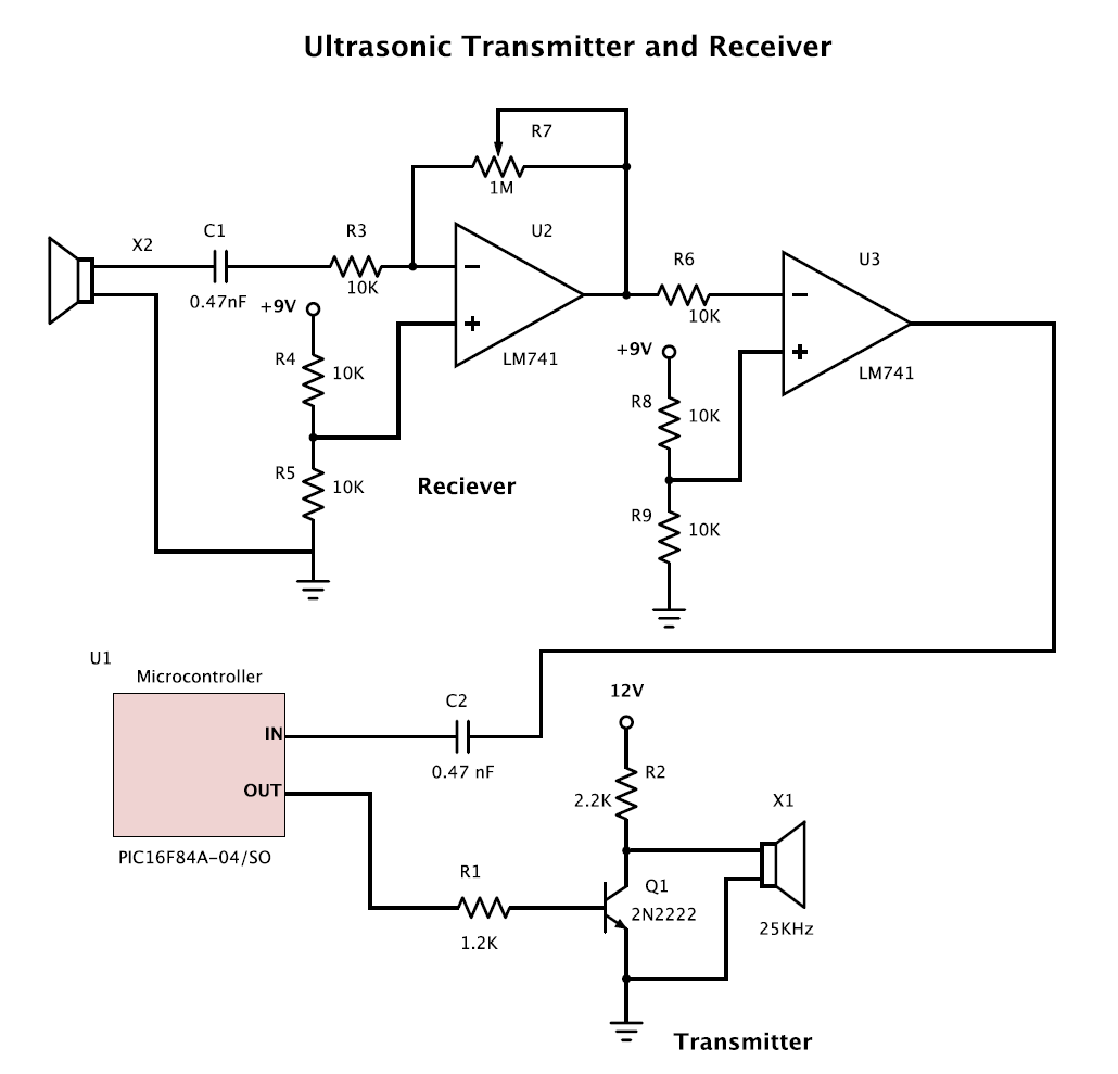
The goal is to create two circuits: one transmitter and one receiver for ultrasound applications. A pair of 25 kHz transmitter and receiver units is already available. To design an ultrasound transmitter and receiver circuit operating at 25 kHz, the...
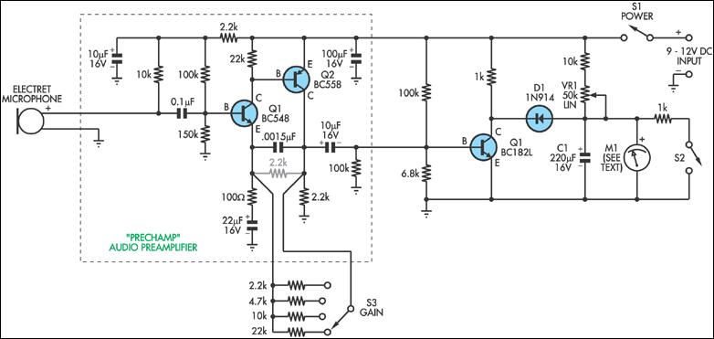
This circuit can be considered a straightforward alternative to the Sooper Snooper device discussed in this issue. It is based on the PreChamp preamplifier featured in the July 1994 issue of SILICON CHIP. This circuit can be utilized to...
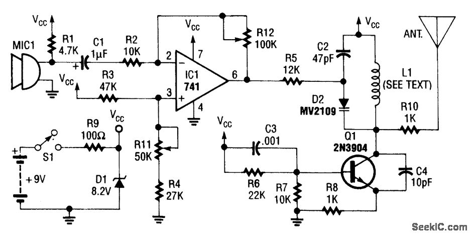
An operational amplifier integrated circuit (741) amplifies the audio signal from microphone 1 (MIC1), with resistor R12 determining its gain. The amplified audio signal is then directed to the oscillator circuit, which includes transistor Q1 and associated components. D2...
This device, available in a Stainless DIL 8 package, is capable of measuring four independent analog voltages ranging from 0 to 5 volts. It transmits the measurement results as four characters via a standard asynchronous serial link. The described device...
This document serves as a compilation of design notes, providing practical details as construction progresses, along with some photographs that will be included in due course. Currently, it functions as a progress report, blending immediate plans with actual construction,...
The original description discusses the increasing rarity of vinyl recordings in the wake of the introduction of CDs. However, it notes the continued utility of a phono preamplifier for the purpose of listening to older vinyl records from a well-maintained...