
Sound Level Indicators

The circuit employs the LM3915, which is specifically designed for LED bar-graph or dot displays. It can drive multiple LEDs in a linear fashion, providing a visual representation of audio levels. The automatic gain control (AGC) circuit enhances the functionality by adjusting the sensitivity based on the input signal, allowing it to effectively handle a wide range of sound levels. The use of a rechargeable battery ensures that the device remains portable, making it suitable for various applications where mobility is essential.
The operational amplifier configuration is critical for signal conditioning, allowing the circuit to respond to audio signals accurately. The inverting nature of the op-amp ensures that the output signal is a direct representation of the input, facilitating precise control over the LED display. The inclusion of Q1 as a voltage reference stabilizes the operation of the transistors, ensuring consistent performance across varying conditions.
The design also considers thermal management, as the LM3915 can generate significant heat when all LEDs are active. The heat dissipation strategy using R16 ensures reliability and longevity of the components. The choice of a Hammond 1591B enclosure is practical, providing both protection and accessibility for the battery and circuit components. Overall, this project exemplifies an effective integration of analog components to create a responsive audio level indicator, showcasing both technical ingenuity and practical design considerations.This project uses an LM3915 bar-graph IC driving two sets of ten LEDs for a 30dB range. The circuit is unique because it has an additional range of 20dB provided by an automatic gain control to allow it to be very sensitive to low sound levels but it increases its range 20dB for loud sounds. The LEDs are operating at 26mA each with the brightness control at maximum, which is very bright. The circuit has a switch to select the modes of operation: a moving dot of light, or a bar with a changing length. My prototype has a little 9V Ni-Cad rechargeable battery in it to be portable and the battery is trickle-charged when the project is powered by a 9V AC-DC adapter.
3) The 2nd opamp stage is a single-supply opamp which works fine with its inputs and output at ground and is used as a rectifier driver with a gain of 1. 8. It is biased at ground. Since it is inverting, when its input swings negative, its output swings positive. a) Q1 is inside the negative feedback loop of the 2nd opamp as a voltage reference for the other two transistors.
Hopefully the transistors match each other. c) Q3 transistor is the automatic gain control. It is also a peak detector but has slower charge and discharge times. It drives the comparators ’ resistor ladder in the LM3915 to determine how sensitive it is. R15 from +5V is in a voltage divider with the ladder ’s total resistance of about 25k and provides the top of the ladder with about +0. 51V when there is a very low sound level detected. Loud sounds cause Q3 to drive the top of the ladder to 5. 1V for reduced sensitivity. 5) The LM3915 regulates the current for the LEDs so they don ’t need current-limiting resistors. In the bar mode with all LEDs lit then the LM3915 gets hot so the 10 ohm/1W resistor R16 shares the heat.
1) The stripboard layout was designed for a Hammond 1591B plastic box with space in the lower end for a rechargeable 9V battery. One bolt holds the circuit board and a second bolt was cut short as a guide. 🔗 External reference
Related Circuits
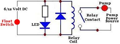
A float switch is a device commonly used to measure the depth or level of liquid in a container. When the liquid rises to the level of the float switch, the float rises, transitioning from a vertical to a...

Creating a sound card is no longer a complex task. By utilizing the PCM2702 integrated circuit from Burr Brown / Texas Instruments, it is possible to design a fully functional USB sound card. This sound card can be powered...
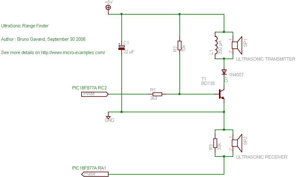
A cat deterrent system utilizing an Arduino, similar to existing models. Detection has been successfully implemented, and it has been determined that an ultrasonic transducer is required to generate the necessary deterrent sound. The proposed cat deterrent system employs an...
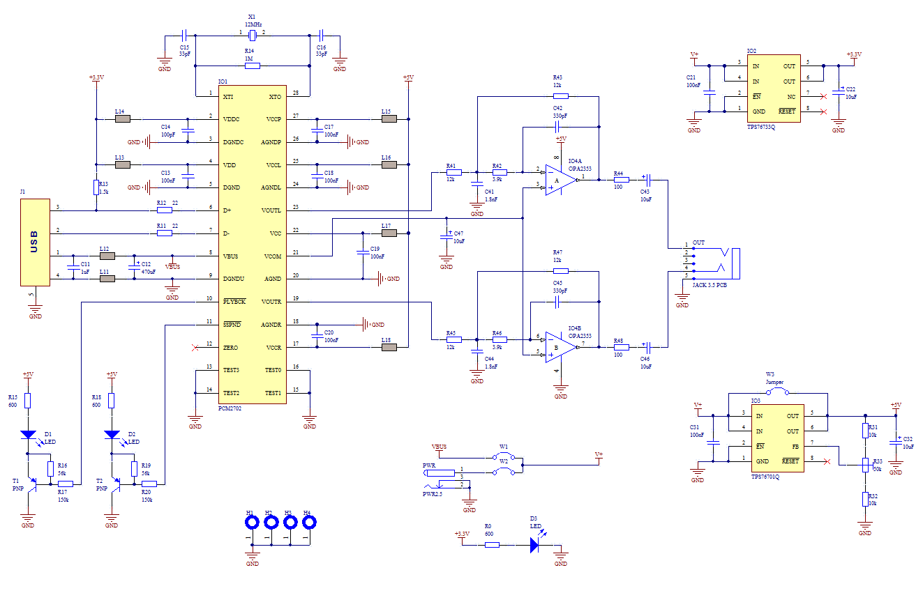
The core of this construction is 16-Bit Stereo Digital-To-Analog Converter with USB interface PCM2702. PCM2702 needs only a few additional parts to work. The schematic is not complex. The sound card can be powered directly from the USB port...
This microphone circuit was submitted by Lazar Pancic from Yugoslavia. The sound card for a PC typically features a microphone input, speaker output, and occasionally line inputs and outputs. The microphone input is designed specifically for dynamic microphones with...
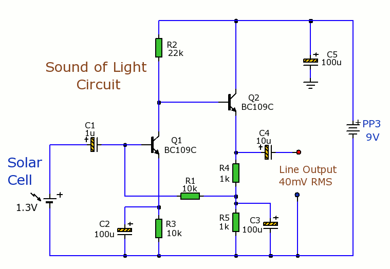
Solar Cells Light-Sound Converter. This is an experimental circuit that converts light into sound. The Solar Cells Light-Sound Converter is an innovative circuit designed to transduce light energy into acoustic signals. This experimental setup utilizes photovoltaic cells to capture ambient...