
Solar Cells Light-Sound Converter
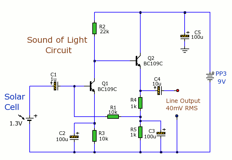
The Solar Cells Light-Sound Converter is an innovative circuit designed to transduce light energy into acoustic signals. This experimental setup utilizes photovoltaic cells to capture ambient light, which is then converted into electrical energy. The generated electrical energy is subsequently processed to produce sound, effectively creating an interface between light and auditory output.
The circuit typically consists of several key components: a solar cell, an operational amplifier, a microcontroller, and a speaker or piezo buzzer. The solar cell serves as the primary energy source, converting incident light into a direct current (DC) voltage. This voltage is then fed into an operational amplifier, which amplifies the signal for further processing.
The microcontroller plays a crucial role in interpreting the magnitude of the voltage generated by the solar cell. It can be programmed to adjust the frequency and amplitude of the sound output based on the intensity of the light detected. This allows for a dynamic auditory experience where variations in light levels correspond to changes in sound characteristics.
Finally, the sound output device, which could be a small speaker or a piezo buzzer, converts the amplified electrical signals back into sound waves, completing the conversion process. The resulting sound can vary from simple tones to more complex audio signals, depending on the design and programming of the microcontroller.
This circuit can be utilized in various applications, including educational projects, sound synthesis, and interactive installations, where it serves as a bridge between visual and auditory stimulation. The experimental nature of this circuit encourages further exploration and development, paving the way for more advanced light-to-sound conversion technologies.Solar Cells Light-Sound Converter. This is experimental circuit that converts light into sound.. 🔗 External reference
Related Circuits
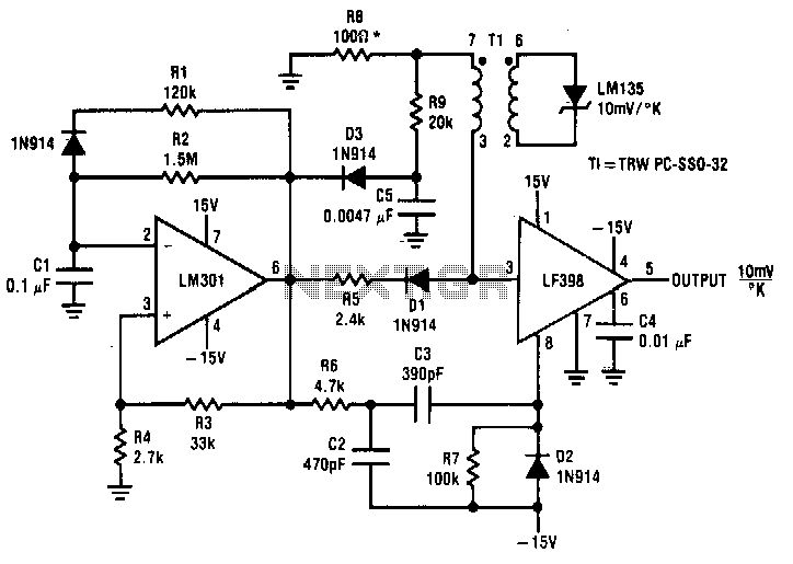
Both converters utilize CMOS inverters. Figure 105-1A illustrates a free-running circuit where both pulse duration and pulse pause are influenced by the temperature of diode D8. This configuration is suitable for applications where synchronization between the converter and other...
This document presents a straightforward and practical schematic for a 12V to 3V converter circuit. The output current of the circuit is approximately 1A. The 12V to 3V converter circuit is typically designed using a linear voltage regulator or a...
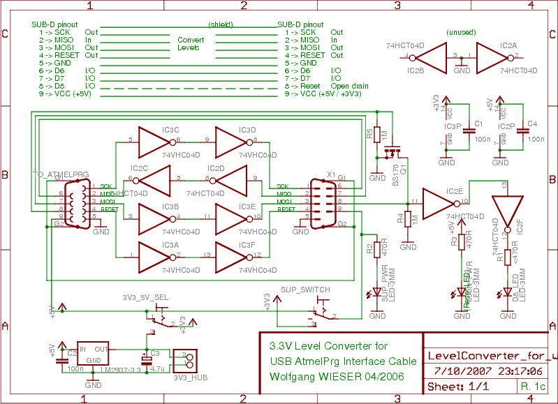
To program devices operating at 3.3V, such as SPI-based AVRs or JTAG-based CPLDs, level conversion is necessary for input and output signal levels. A 5V input may not register as HIGH at 3.3V, and a 3.3V device can be...
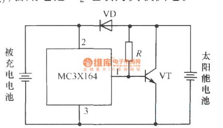
The following circuit illustrates a current-limited solar battery charger circuit diagram. This lead-acid or Ni-Cd battery charger circuit diagram utilizes solar energy to charge a 6-volt, 4.5 Ah rechargeable battery for various applications. It represents a straightforward solar battery...
Below is the schematic diagram of an audio input module. This module is capable of producing a DC output voltage that is proportional to the amplitude of the input signal. The audio input module typically consists of several key components...
An article detailing the construction of a small solar panel from scratch. The process of building a small solar panel from scratch involves several key components and steps that are crucial for achieving an efficient and functional solar energy system....
Warning: include(partials/cookie-banner.php): Failed to open stream: Permission denied in /var/www/html/nextgr/view-circuit.php on line 713
Warning: include(): Failed opening 'partials/cookie-banner.php' for inclusion (include_path='.:/usr/share/php') in /var/www/html/nextgr/view-circuit.php on line 713