
Sound Level Meter

The sound level meter circuit utilizing the LM3915 integrated circuit is designed to provide a visual representation of audio signal levels. The LM3915 is a bar graph or LED dot display driver that can indicate voltage levels corresponding to audio signals, making it suitable for applications in audio equipment and sound measurement.
The circuit typically consists of the LM3915 IC, a power supply, resistors, capacitors, and a display consisting of either LEDs or an LCD. The input audio signal is fed into the circuit through a microphone or audio amplifier output. The IC processes the incoming audio signal and converts it into a proportional voltage level.
The configuration of the LM3915 can be set to operate in either bar graph mode or dot mode, depending on the application requirements. The output pins of the IC are connected to a series of LEDs, which light up in response to the input audio level. This visual feedback allows users to easily monitor sound levels in real-time.
To enhance the functionality of the sound level meter, additional components such as a filter circuit may be included to eliminate noise and ensure accurate readings. The circuit can also be calibrated to adjust the sensitivity of the meter, allowing for precise measurement across different audio environments.
In summary, the sound level meter circuit utilizing the LM3915 is an effective tool for measuring and displaying audio levels, making it valuable in various audio applications, from professional sound systems to home audio equipment.A sound level meter circuit with diagram and schematic using IC LM 3915,which is an audio level measurement chip.Used to display amplifier sound level or a microphone sound level.. 🔗 External reference
Related Circuits

This circuit is designed to measure the inductance of an inductor labeled LX. The output of the circuit generates a TTL square wave, with its frequency being directly related to the inductance being measured. The output from the inductance...
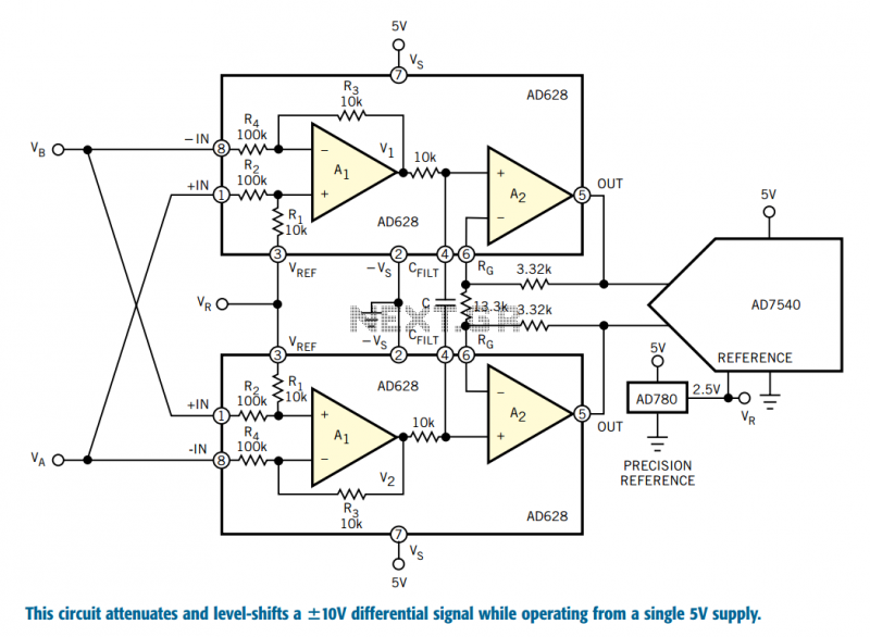
Designers who build equipment for the industrial market share a widespread problem. At one extreme, they must build equipment that supports ±10V bipolar voltages, often riding on a high common-mode level, a requirement enforced by 30 years of legacy...
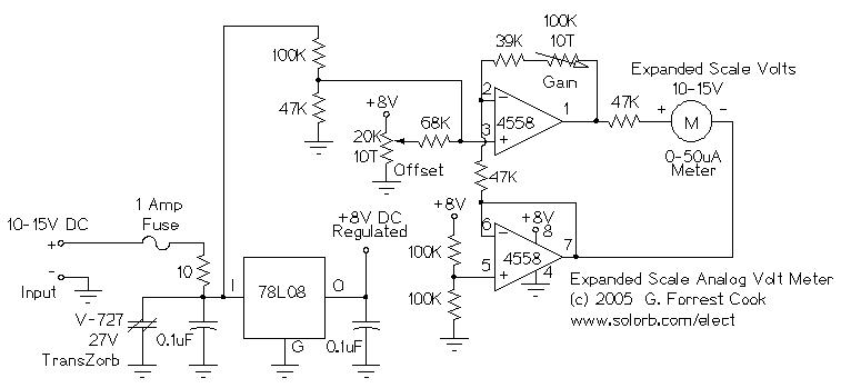
This circuit is designed to measure the voltage of a 12V nominal lead-acid rechargeable battery system. While it was specifically created for solar-powered systems, it is versatile enough for use in automotive or other 12V applications. Lead-acid batteries typically...
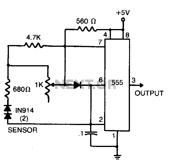
The sensor comprises two series-connected 1N914 diodes, which are part of the circuit of a 555 multivibrator. When wired as illustrated, the output pulse rate is proportional to the temperature of the diodes. This output is then fed into...
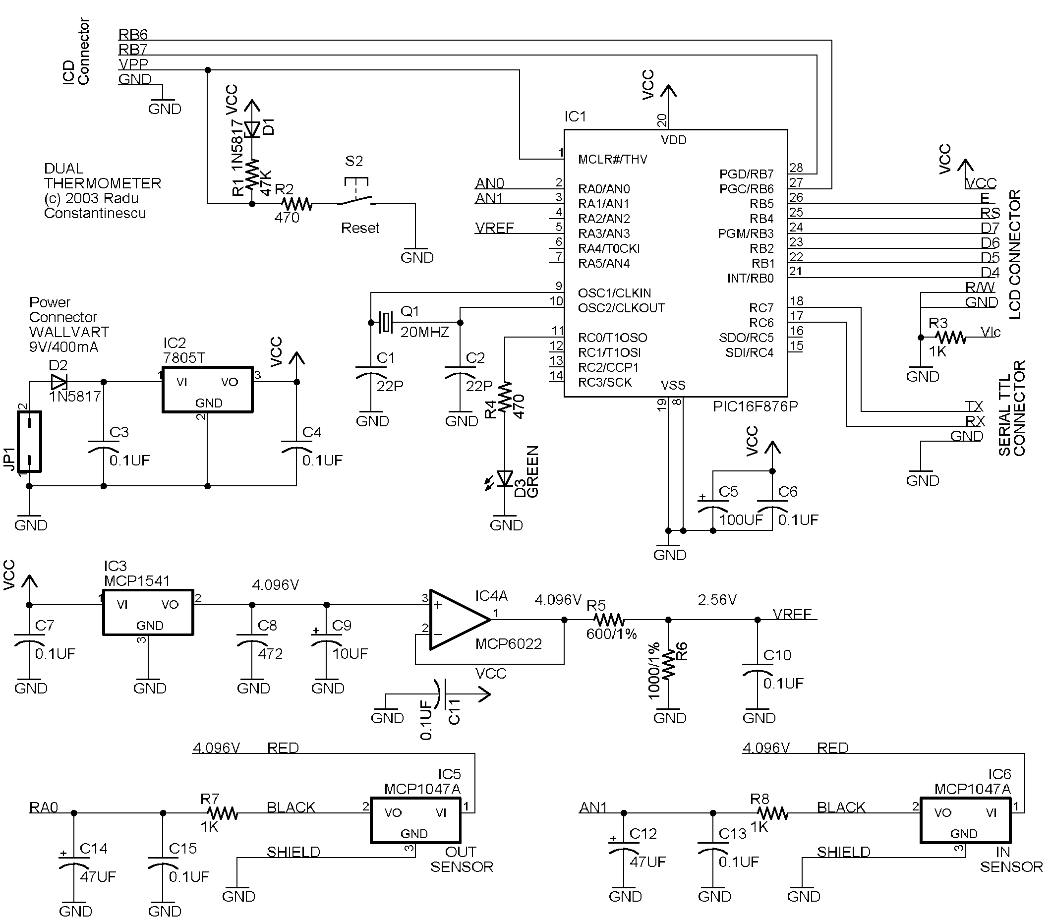
This circuit utilizes a PIC16F876 microcontroller, two MCP1047A temperature sensors, an MCP1541 voltage reference, and a MCP6022A operational amplifier. The display is a 2-row HD74780-based 2x16 character display (SII L1652BIJ2), though any HD74780 compatible display can be used. The...
The CA3189 integrated circuit (IC) incorporates a symmetrical limiter, a phase demodulator, an audio amplifier, and a logarithmic detector-amplifier. The logarithmic detector-amplifier is particularly noteworthy for enhancing the logarithmic signal meter of shortwave receivers, thereby improving signal reading accuracy....