
Digital thermometer

The described sensor utilizes two 1N914 diodes connected in series to form a temperature-sensitive component within a 555 timer-based multivibrator configuration. The 555 timer operates in astable mode, generating a continuous square wave output. The frequency of this output is influenced by the forward voltage drop across the diodes, which varies with temperature. As the temperature increases, the forward voltage drop decreases, resulting in an increase in the output frequency of the multivibrator.
In this configuration, the diodes serve as temperature sensors, with their characteristics allowing for a direct correlation between temperature variations and the output frequency. The output pulse rate from the 555 timer is then directed to a frequency-counting circuit, which can be implemented using a microcontroller or a digital frequency counter. This circuit counts the number of pulses in a given time frame, translating the frequency into a readable temperature value.
The frequency-counting circuit may include components such as a microcontroller with an integrated timer or an external counter IC. The microcontroller can be programmed to convert the frequency into a temperature reading, which can then be displayed on an LCD or sent to a computer for further analysis.
Overall, this setup provides a simple yet effective method for temperature measurement, leveraging the characteristics of the 1N914 diodes and the versatile 555 timer to create a reliable temperature-sensing circuit.The sensor consists of two series-connected lN914s, part of the circuit of a 555 multivibrator. Wired as shown, the output pulse rate is proportional to the temperature of the diodes This output is fed to a simple frequency-counting circuit.
Related Circuits
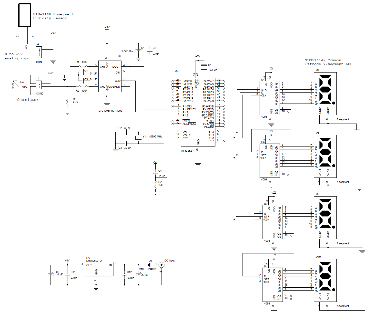
This circuit features a microcontroller AT89S52 thermometer paired with an LTC1298 12-bit ADC. The program is written in C language and incorporates digital filtering along with an interface for an LED display. The temperature readings have a sensitivity of...
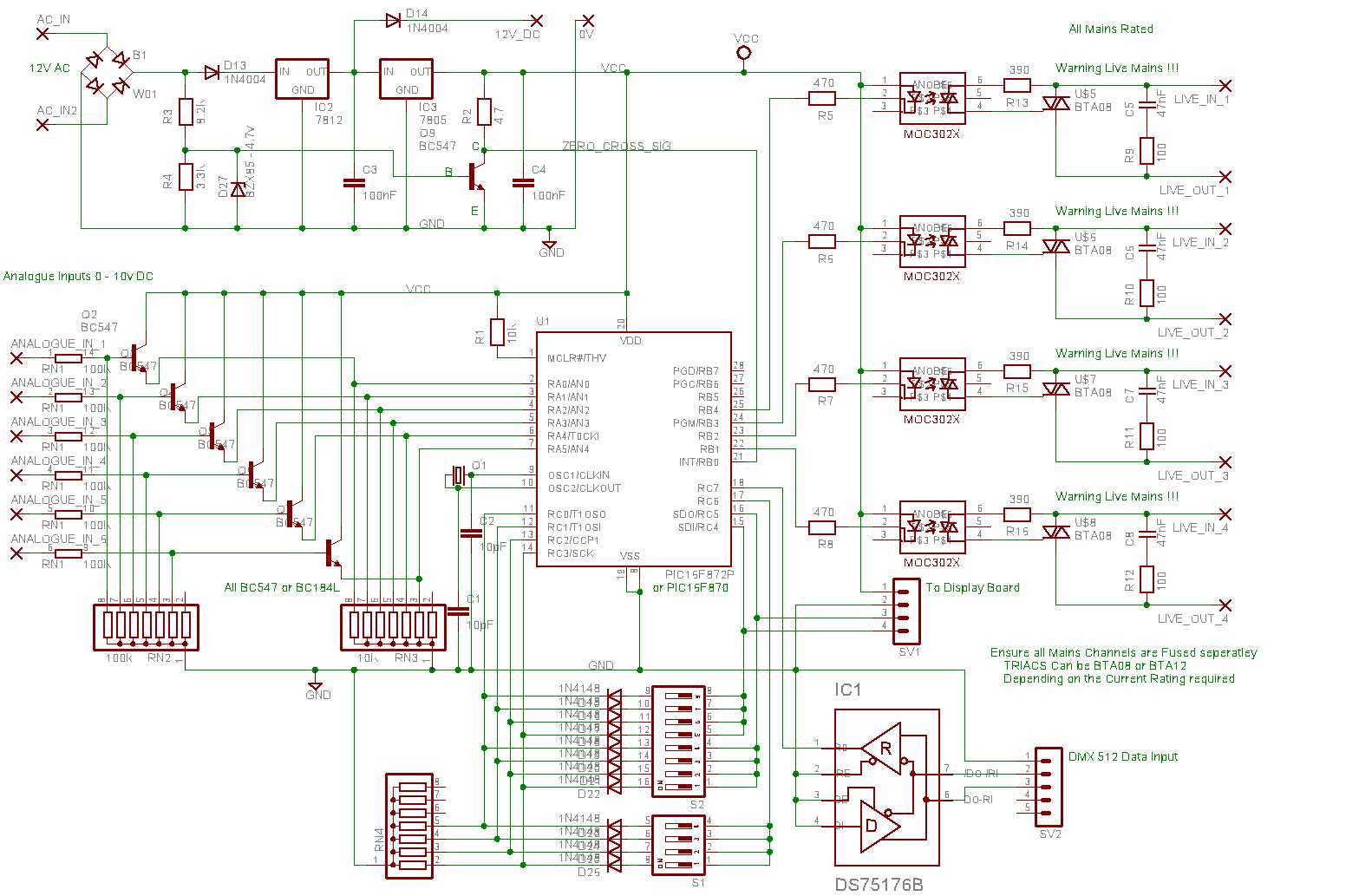
This unit receives DMX 512 data and Analogue (0-10V) data and uses these to phase angle control mains output. Features: DMX 512 data Input. Analogue (0-10V) DC Input. 4 Output channels. Remotely programmable Internally saved Presets. 3 Modes of...
This project utilizes the ISD2560P integrated circuit (IC), which enables the recording of 60 seconds of audio and subsequent playback with high fidelity. The schematic indicates that the input source is an electret microphone. If a dynamic microphone is...
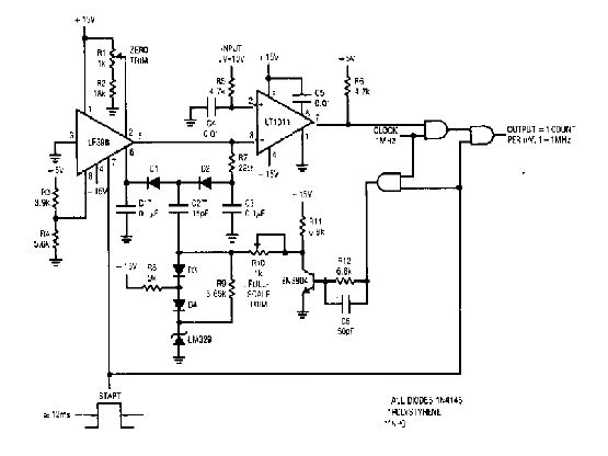
The simple 4-digit converter circuit has an output count of 1, designed to operate within a frequency range of f-IMHz to 10.000. All diodes used in the circuit are IN4146, and the capacitors are made of `POLYSTYRENE` NPO. The...
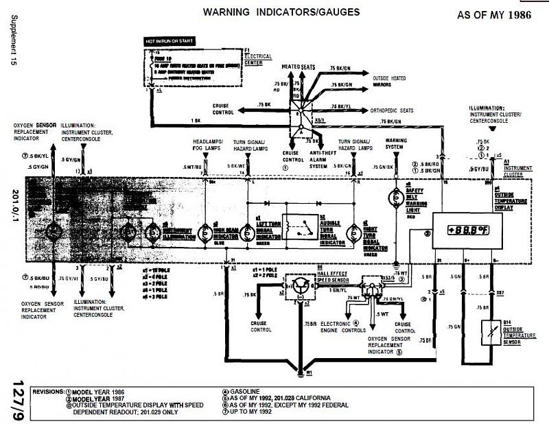
The 1989 2.6 outside thermometer (Celsius) has malfunctioned and stopped displaying readings. A replacement unit was sourced from an eBay seller. The malfunctioning outdoor thermometer likely employs a thermistor or a similar temperature-sensing component to measure ambient temperature. In a...
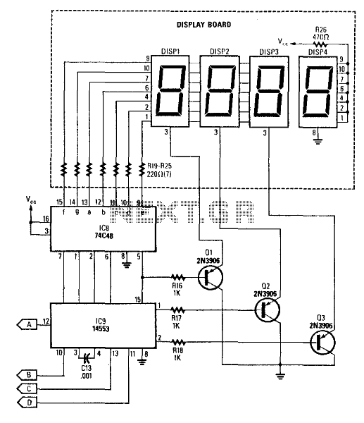
This circuit produces a readout for the digital tachometer circuit. IC9 is a 3-digit LED display driver, counter, and latch. IC8 drives the common-cathode LEDs, which are enabled by Q1, Q2, and Q3. See page 268, Fig. 46-5 for...