
Sound level monitor

The loudness detector circuit utilizes the 555 timer IC, which is a versatile and widely used component in various electronic applications. When configured as a Schmitt trigger, the 555 IC provides hysteresis in the output, which helps to eliminate noise from the input signal and ensures stable switching behavior.
In this configuration, the input voltage is continuously monitored. When the input voltage rises above the threshold set by the resistor R4, the output of the 555 IC switches from a high state (logic level '1') to a low state (logic level '0'). This transition can be used to trigger other circuits or devices, such as an LED indicator or a sound alert, indicating that a certain loudness level has been detected.
The threshold voltage is critical for the operation of the loudness detector. It is determined by the resistor R4, which is part of a voltage divider network. By adjusting the resistance of R4, the sensitivity of the detector can be modified, allowing it to respond to different levels of input voltage. This feature makes the circuit adaptable for various applications, such as audio processing, sound level monitoring, or automatic gain control systems.
In summary, the loudness detector circuit employing a 555 IC as a Schmitt trigger provides a reliable means of detecting loudness levels by utilizing a threshold voltage established by the resistor R4, thereby facilitating various audio-related applications.Loudness detector consists of a 555 IC wired as a Schmitt trigger. The output changes state—from high to low—whenever the input crosses a certain voltage That threshold voltage is established by the setting of R4.
Related Circuits
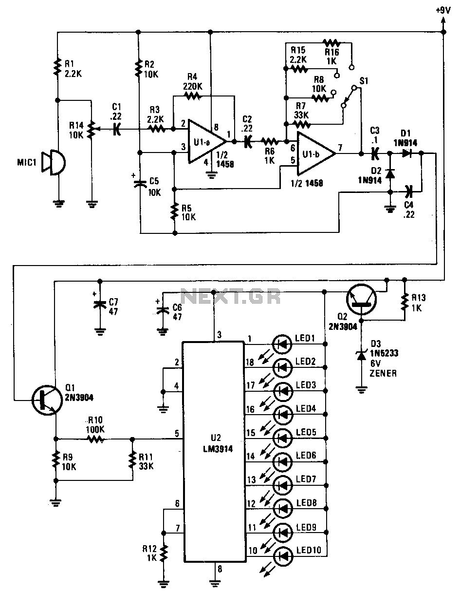
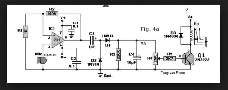
Sounds are captured by MIC1 and sent to the input of the first operational amplifier (op-amp). The signal is subsequently directed to the input of the second op-amp, U1B, where it is amplified by a factor ranging from 1...
R1 = 470K, N1, N2 = MC14093B, R2 = 15M, T1 = 2N3906 (also compatible: PN200, 2N4413), C1-C4 = 2.2nF (NTE159, ECG159, BC557, BC157, TUP), D1 = 1N4001, Ry = Relay (12V or matching supply voltage), D2, D3 =...
The particular circuit does not have the requirement to replace the trade decoders Surround, because they have many more facilities and possibilities. It gives, however, the possibility in many trials with this article of decoding. The coding in Stereo...

This design idea explains how to develop a water sensor circuit that can monitor upper and lower water levels. The water sensor circuit is designed to detect and monitor water levels within a specified range, providing feedback when the water...
The circuit diagram for a dynamic toy that produces eight sounds and five flashing lights is illustrated. It features the HFC3018 module, capable of generating eight distinct sounds, including step gunfire, aviation gunfire, game sight, telephone sight, bomb 1,...
A circuit that enables control of a relay in response to sound from a non-amplified sound source, such as a computer, CD player, or a Digital Sound Recorder board. This circuit accepts audio input from any non-amplified sound source,...