
Water-Level Sensor Uses Hysteresis

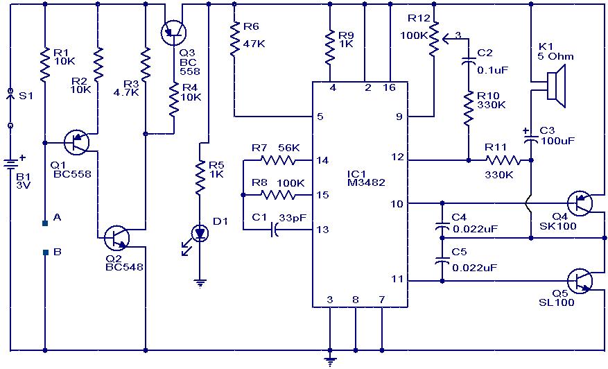
The water sensor circuit is designed to detect and monitor water levels within a specified range, providing feedback when the water level exceeds or falls below predetermined thresholds. The circuit typically consists of several key components: water level sensors, a microcontroller or comparator, power supply, and output indicators such as LEDs or alarms.
The water level sensors can be resistive or capacitive, depending on the application. Resistive sensors utilize two conductive probes placed at the desired upper and lower water levels. When water bridges the gap between the probes, it completes a circuit that can be read by the microcontroller or comparator. Capacitive sensors, on the other hand, measure the change in capacitance caused by the presence of water, offering a non-contact method of detection.
The microcontroller or comparator is programmed to compare the readings from the sensors against set thresholds. When the water level reaches the upper threshold, the circuit can activate an output device, such as a pump or an alarm, to indicate that the water level is too high. Conversely, if the water level drops below the lower threshold, the circuit can trigger another output to alert users or activate a refill mechanism.
Power supply considerations are crucial for ensuring reliable operation. The circuit can be powered by a DC source, such as batteries or a wall adapter, with appropriate voltage regulation to match the components' specifications.
Output indicators, such as LEDs, can provide visual feedback regarding the water levels. For instance, a green LED might indicate normal water levels, while a red LED could signal that the water level is too high or too low.
Overall, this water sensor circuit is a practical solution for applications in aquariums, water tanks, or industrial processes where monitoring water levels is essential for operational efficiency and safety.This design idea explains how to develop a water sensor circuit that can monitor upper and lower water levels 🔗 External reference
Related Circuits
An affordable electronic device useful for demonstrating electrostatic phenomena. Ahern's instrument serves as an effective substitute for the tonal electrostatic voltmeter. It provides polarity-dependent information about electric charge motion that conventional instruments do not offer. This apparatus is easy...
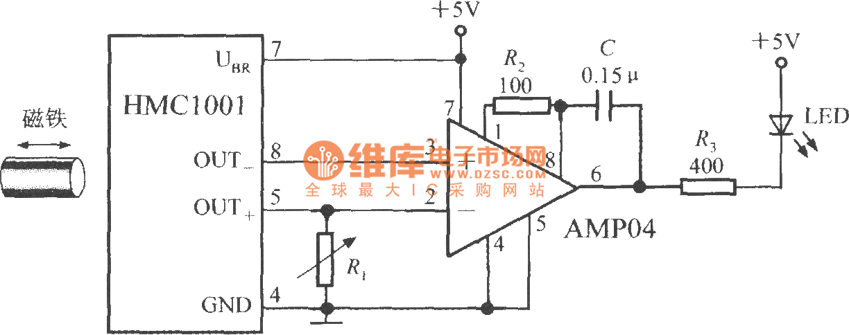
The proximity switch circuit consists of the HMC1001 sensor, operational amplifier (AMP04), and a light-emitting diode (LED). The operational amplifier functions as a comparator. When a magnet, measuring between 6mm and 12mm, is moved to a predetermined position near...
All distances mentioned can vary depending on the infrared transmitting and receiving LEDs used and are significantly affected by the color of the reflecting surface. Black surfaces greatly reduce the device's sensitivity. This circuit can also be applied in...
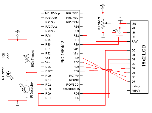
The circuit for the Digital Tachometer/RPM Counter consists of only a few devices. Wire them up according to the following circuit diagram. The PIC used is on a demonstration board, which means the clock, power, and ground pins are...
This is a hobby circuit designed as a water or liquid sensor. Its primary function is to activate an alarm when water or liquid is detected at its probes. The water sensor circuit typically consists of a few essential components,...
This DIY magnetic field sensor circuit is straightforward and capable of detecting both static magnetic fields and those that vary at audio frequencies. The unit is designed to be user-friendly and efficient. The magnetic field sensor circuit typically employs a...