
Sound Operated Flip Flop Based On The LM324 IC

The Sound Operated Flip Flop circuit utilizes the LM324 operational amplifier, which consists of four independent, high-gain, frequency-compensated operational amplifiers. In this configuration, the circuit is designed to respond to audio signals captured by a condenser microphone. The microphone converts sound waves into an electrical signal, which is then amplified by the operational amplifier.
The circuit typically includes a threshold detection mechanism, which allows it to distinguish between ambient noise and significant sound events. When the sound level exceeds a predefined threshold, the output of the operational amplifier changes state, triggering the flip-flop. This flip-flop can be configured to control various outputs, such as LEDs or relays, providing a visual or functional response to the detected sound.
Power supply considerations for the LM324 IC should ensure that the voltage levels are appropriate for the operational amplifier's specifications, typically ranging from 3V to 32V. Additionally, bypass capacitors should be placed close to the power supply pins of the IC to minimize noise and stabilize the power supply.
Overall, this circuit is a practical application of sound detection and can be utilized in various projects, such as sound-activated switches, alarms, or interactive devices, enhancing user engagement through auditory stimuli.The following circuit shows about Sound Operated Flip Flop. This circuit based on the LM324 IC. Features: condenser microphone is used for picking .. 🔗 External reference
Related Circuits
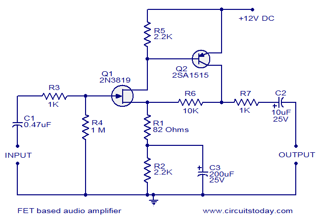
This circuit is a low-noise audio preamplifier that utilizes one FET and one BJT. The audio signal to be amplified is connected to the base of FET Q1 through capacitor C1 and resistor R3. The base of transistor Q2...
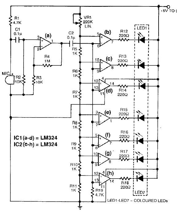
This sound level meter circuit can be used to control the intensity of a sound recording or in a disco. It has 5 measurement domains between 70 and 120 dB. The sound level meter circuit is designed to measure sound...
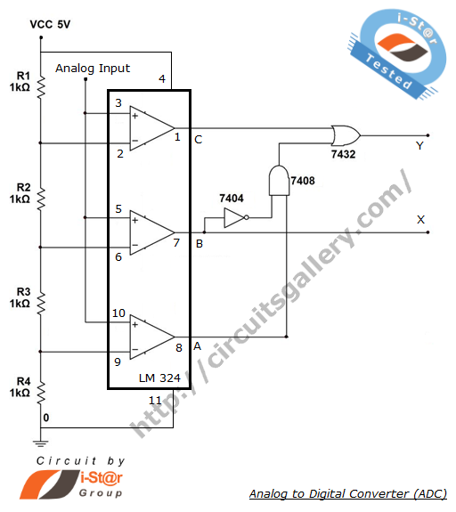
The process of converting an analog voltage into an equivalent digital signal is known as Analog to Digital Conversion (ADC). An ADC is an electronic circuit that converts its analog input to a corresponding binary value. The output depends...
The operation of the circuit is divided into three parts: low frequency production, high frequency manufacturing, and low frequency extension. The described circuit functions by segmenting its operation into three distinct sections, each serving a specific purpose in the overall...
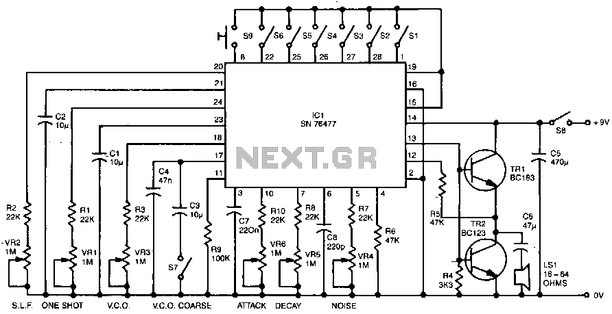
Six preset controls and seven selector switches enable a vast range of different sounds to be produced and altered at will. Such sounds as steam trains chuffing, helicopters flying, bird chirping, and machine guns firing are possible, as well...
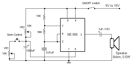
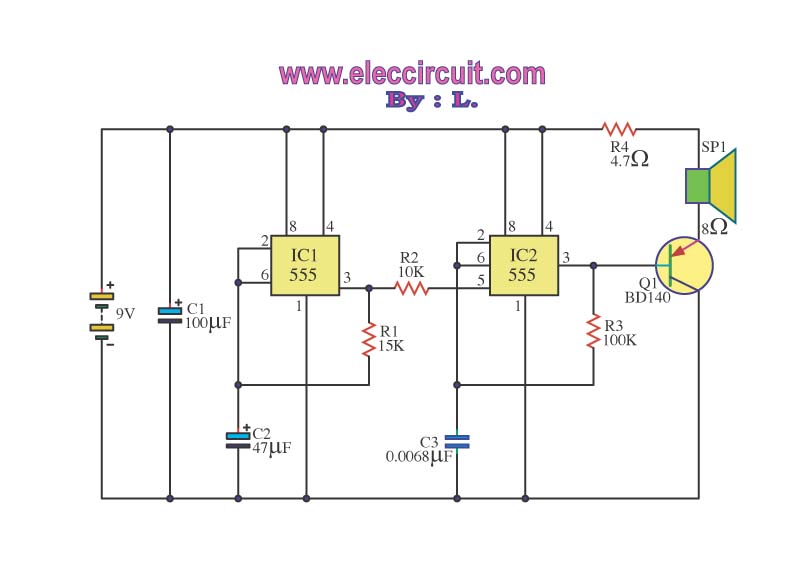
The circuit diagram of an electronic siren based on the NE555 timer produces a sound similar to that of a factory siren. The NE555 timer IC functions as an astable multivibrator with a center frequency of approximately 300 Hz....