
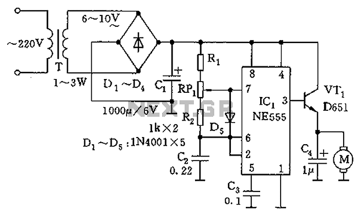
Two sirens sound with ic 555

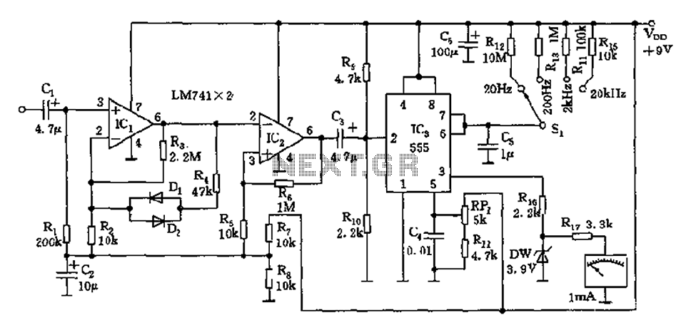
The described circuit functions by segmenting its operation into three distinct sections, each serving a specific purpose in the overall system. The first section focuses on low frequency production, which is responsible for generating signals within a lower frequency range. This part of the circuit may utilize components such as resistors, capacitors, and inductors to create oscillations or modulate signals effectively.
The second section of the circuit is dedicated to high frequency manufacturing. This part is designed to produce signals at higher frequencies, which may involve the use of specialized components such as RF amplifiers, oscillators, and filters. These components are essential for ensuring that the high frequency signals are generated accurately and efficiently, enabling the circuit to function properly in applications that require rapid signal processing.
The third section deals with the extension of low frequency production. This phase may involve amplifying or modifying the low frequency signals generated in the first section to enhance their amplitude or adjust their characteristics for better performance. This could include the use of operational amplifiers or other signal conditioning components.
Overall, the circuit's design allows for a versatile approach to signal generation and manipulation across different frequency ranges, making it suitable for various electronic applications. Each part of the circuit must be carefully designed and integrated to ensure seamless operation and optimal performance.Operation of the circuit. Circuit is divided into three parts: low frequency production. The manufacturing high frequency and extension of production low. 🔗 External reference
Related Circuits
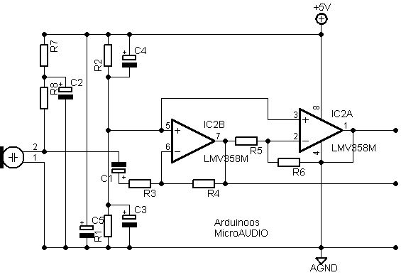
After conducting new experiments on sound analysis, a different design for the microphone amplifying section has been developed. The entire circuit is powered by a clean voltage supply ranging from +5V to +12V, which is filtered by capacitor C5....
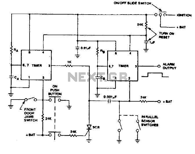
The 555 timer generates a reliable delay, enabling the driver to deactivate the alarm and eliminating the need for an external control switch that could be compromised. Additionally, the RCS prevents the activation of timer B unless it is...
The circuit is a direct-reading frequency meter that utilizes an amplifier and a one-shot trigger circuit, along with table-top components. It is capable of directly detecting a 1mA signal at the read head, with a maximum signal frequency of...
This circuit generates a two-tone effect similar to the sound of a cuckoo. It can be utilized for doorbells or other applications due to its integrated audio amplifier and loudspeaker. When used as a sound effect generator, it can...
The circuit utilizes a 555 timer as the core component to create an astable multivibrator. The oscillation period T is given by the formula T = 0.693 (R1 + 2R2) C1, which corresponds to an oscillation frequency of approximately...
The objective of this lab is to create a decimal counter that counts from 0 to 99 using the 80X51 microcontroller. A C program must be written for this purpose, which will then be compiled using the C51 compiler...