
Spectrum Analyzer Adapter for Oscilloscopes

The spectrum analyzer adapter circuit is engineered to enhance the capabilities of an oscilloscope, allowing it to perform frequency analysis of input signals. The primary components of this circuit typically include resistors, capacitors, operational amplifiers, and possibly a microcontroller for signal processing and display.
The circuit operates by taking an input signal, which is then filtered through a series of bandpass filters. These filters are designed to isolate specific frequency ranges, enabling the oscilloscope to display the amplitude of signals within those ranges. Each filter stage contributes to the overall frequency response of the circuit, ensuring that only the desired frequencies are passed to the output.
Operational amplifiers are employed to amplify the filtered signals, providing sufficient gain for accurate display on the oscilloscope. The configuration of these amplifiers can be adjusted to accommodate various input signal levels, ensuring versatility in applications.
Additionally, the circuit may include a display interface, such as an LCD or LED array, to provide real-time visual feedback of the frequency analysis. This feature allows users to easily interpret the signal characteristics without needing to constantly refer to the oscilloscope screen.
Power supply considerations are also critical for the proper functioning of the spectrum analyzer adapter. A stable power source is necessary to maintain the integrity of the signal processing and avoid noise interference that could affect measurement accuracy.
Overall, this spectrum analyzer adapter circuit serves as a valuable tool for engineers and technicians, facilitating detailed analysis of signal frequencies and enhancing the functionality of standard oscilloscopes.The circuit shown in the following schematic diagram is a simple spectrum analyzer adapter circuit for oscilloscopes. This circuit can be used for scanning or.. 🔗 External reference
Related Circuits
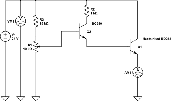
The device shows a voltage of 24V at no load on pins +4, 5 and -7, 8. This configuration is referred to as a passive power injector. When a current draw of 1A was attempted from the device, it...
The Lazy Adapter is composed of a 20 pin DIP socket, a 20 pin DIP header, and a 6 pin ISP header, and a small phenolic circuit board to hold them all together. The green fiberglass PCB is a...
This circuit utilizes the LT1074CT switching regulator integrated circuit (IC). For a more comprehensive explanation of the design, it is recommended to refer to Application Note AN35 published by Linear Technology. The schematic illustrates the LT1074CT functioning as a...
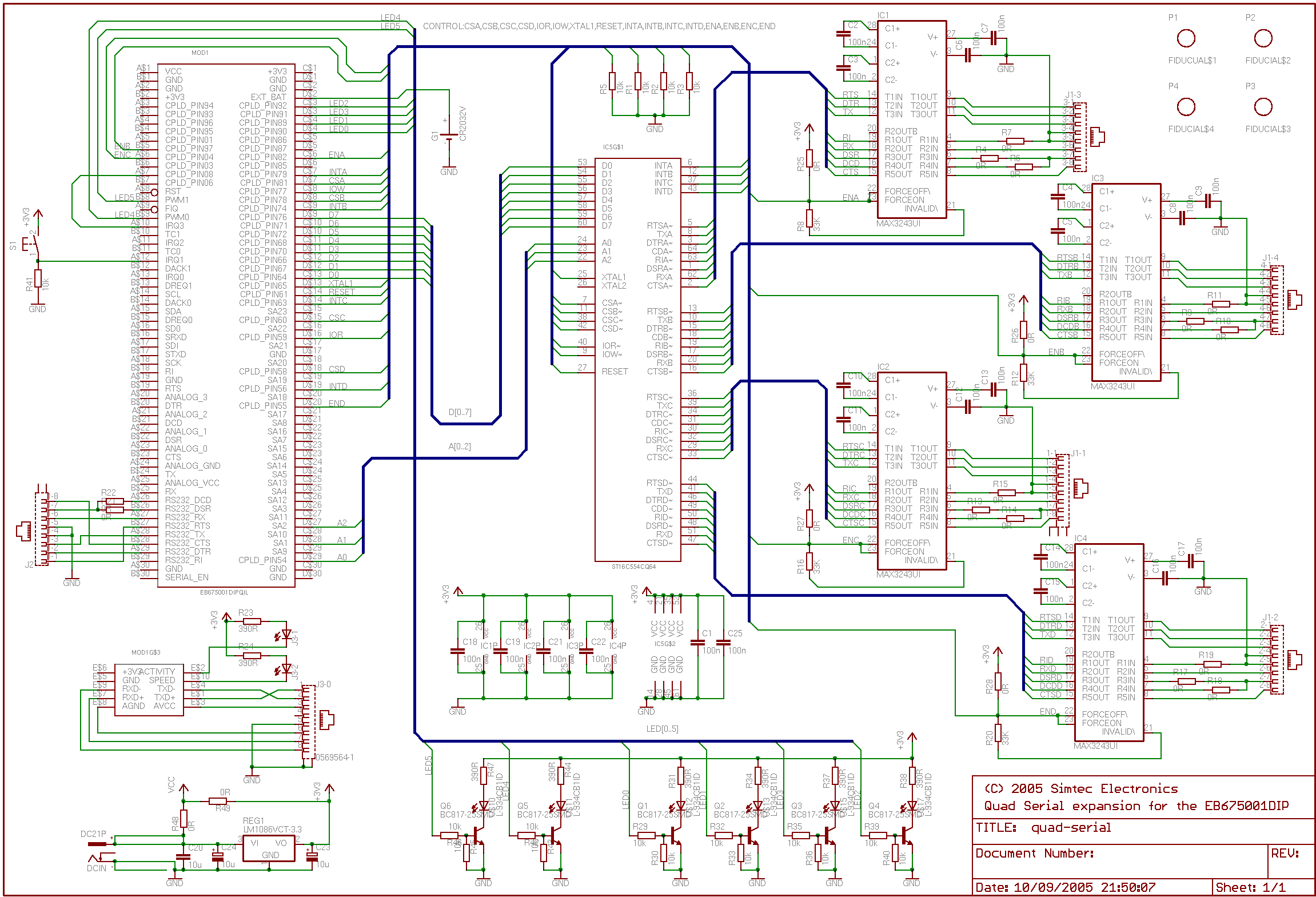
This application note details the integration of a quad serial controller into the EB675001 Module. A multi-source quad Universal Asynchronous Receiver and Transmitter (UART), specifically the 16554 type, was chosen to facilitate component sourcing and implementation. The RS232 line...
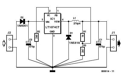
This 3-volt car adapter circuit is based on a standard LT1074CT switching regulator IC. The schematic shows the LT1074CT used as a positive step-down regulator. The 3-volt car adapter circuit employs the LT1074CT, which is a high-efficiency switching regulator capable...
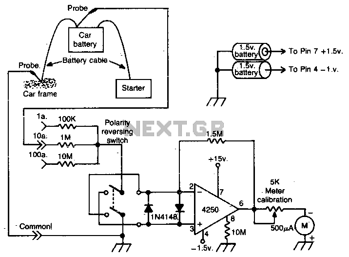
This operational amplifier (op-amp) analyzer is designed to measure the current drawn by any device in a vehicle. It operates by detecting the minute voltage that develops across the battery cables when current flows. To calibrate the unit, the current...