
3 volts car adapter using lt1074ct

The LT1074CT is a versatile switching regulator capable of efficiently converting higher DC voltages to lower ones, making it ideal for applications requiring stable voltage supplies from car batteries. The buck converter topology employed in this design allows for high efficiency and reduced heat generation, which is critical in automotive applications where space and thermal management are concerns.
The feedback mechanism is crucial in ensuring that the output voltage remains stable despite variations in load conditions. The resistors R1, R2, and R3 form a voltage divider that feeds back a portion of the output voltage to the F/B pin, allowing the LT1074CT to adjust its duty cycle accordingly. This feedback loop is essential for maintaining the desired output voltage of +3 V, regardless of fluctuations in input voltage or load current.
Inductor L1 plays a vital role in energy storage during the switching process. As the LT1074CT switches on, current flows through L1, storing energy in the magnetic field. When the switch turns off, the inductor releases this stored energy to the output capacitor C1 and the load, ensuring a continuous supply of current. The choice of inductor value is critical, as it affects the ripple current and overall efficiency of the converter.
Capacitor C1 not only serves to decouple the output load but also smooths out voltage fluctuations, ensuring a stable output voltage. The input capacitor C3 is equally important, as it helps filter out high-frequency noise and provides a stable voltage to the LT1074CT, enhancing the overall performance of the circuit.
In summary, this circuit provides an effective solution for powering low-voltage devices from a car's electrical system, ensuring that children can use their devices without concern for battery life or voltage stability during long journeys. The design emphasizes efficiency, stability, and safety, making it a practical choice for automotive applications.This circuit is based on a standard LT1074CT switching regulator IC. For sure, Application Note AN35 published by Linear Technology describes the design far more elegantly than the author could in this short article. Interested readers are therefore strongly advised to get a copy of AN35. The schematic shows the LT1074CT used as a positive step-do wn or buck` converter. The switcher` is used to convert a +12-volt car battery voltage down to +3 volts for use with the personal hi- ¬`s and hand-held games for the author`s two boisterous children on long car journeys. Note at under ten years of age, children will rarely be hi- ¬ a ¬cionado`s and are generally not concerned with any noise generated by the switcher circuit.
The circuit is connected to the car +12-V system via the cigarette lighter socket ” is advisable to use a fused version of the cigarette lighter plug. The +12-V arrives on the board via screw- terminal block J2. Diode D2 provides a reverse voltage protection, while C3 decouples the input to the switcher IC. The LT1074CT briskly switches the supply voltage on and off in response to the signal applied to its F/B input, to the extent that the average output voltage is at the required level.
The values of potential divider resistors R1-R3 have been chosen to attenuate the output voltage so that there is 2. 5 V at the F/B pin. The difference between the attenuated output voltage and the internal 2. 5-V reference is used to control the modulation effect of the switcher. Components R2 and C2 provide frequency stabilization for the feedback loop. Inductor L1 along with the LT1074CT form the main switching components, while C1 provides decoupling for the output load.
The 3-V output voltage is taken from screw terminal J1. With this circuit built, boxed up and installed in your car, you can look forward to possibly your first quiet` long car journey. 🔗 External reference
Related Circuits

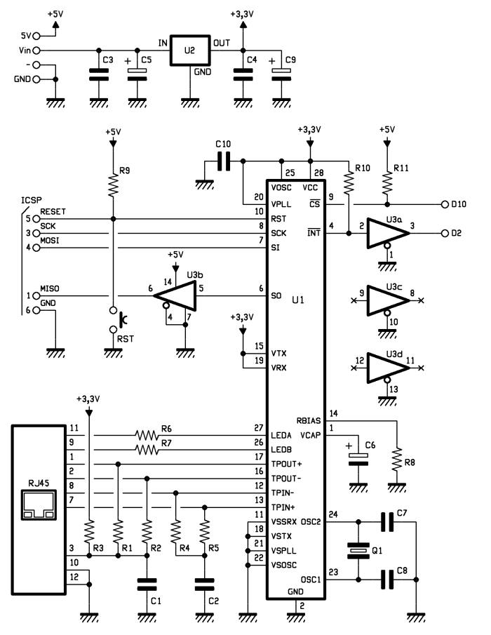
Designing and building a USB sound card has become straightforward with the PCM2702 integrated circuit from Texas Instruments. The PCM2702 is a 16-bit digital-to-analog converter featuring two digital-to-analog output channels. Its integrated interface controller adheres to USB 1.0 standards....
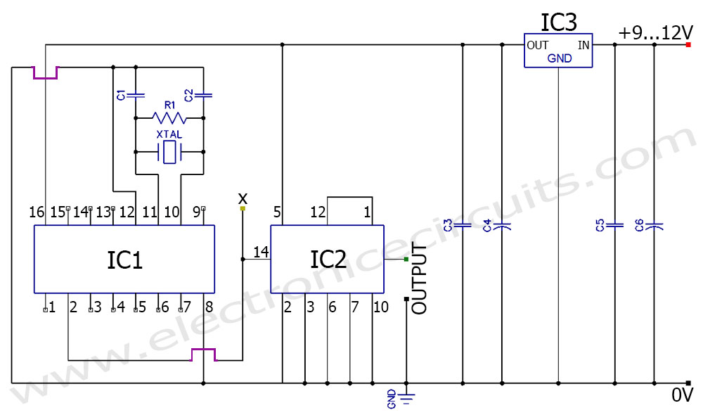
A frequency generator circuit capable of producing 50 Hz and 60 Hz outputs using a crystal oscillator. This oscillator can be utilized to generate precise frequency signals. This frequency generator circuit employs a crystal oscillator as its core component, which...
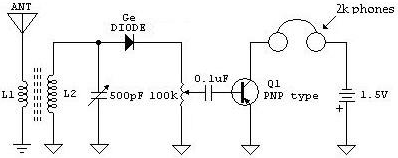
The following schematic illustrates a Crystal Radio Receiver Circuit Diagram that incorporates audio frequency (AF) amplification utilizing a Germanium transistor. The inclusion of AF amplification enhances the audio output quality. The Crystal Radio Receiver Circuit is a simple yet effective...
One of the most interesting shields that can be mounted on the Arduino platform is the Ethernet shield, as it enables numerous networking applications such as remote control of systems and users, web access, data publication, and more. The...
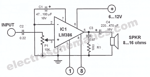
This car stereo booster utilizes an LM2896 integrated circuit, which features two amplifiers. It operates with supply voltages ranging from 3 to 15 volts. The power output is 2.5 watts per channel when connected to an 8-ohm load at...
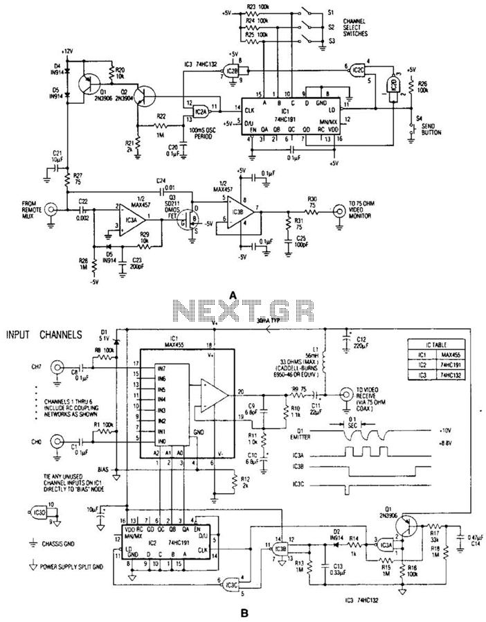
In the video system illustrated in Figures A and R, a single coaxial cable transmits power to a remote location, selects one of eight video channels, and returns the selected signal. This system can choose from several remote surveillance...