
Speech Recorder (ISD2560)
")
The circuit described incorporates a voice recording and playback system using the ISD2560 IC, which facilitates the recording and playback of audio messages. The system is controlled by two pushbuttons (S1 and S2) and a change-over switch (S3) that allows for different operational modes: Play and Record.
The S1 pushbutton serves dual functions; it initiates playback when in Play mode and pauses playback when pressed again. The S2 pushbutton is used for stopping the playback or resetting the system. To delete a recorded message, S2 must be pressed twice in quick succession, which clears the stored audio data.
The change-over switch (S3) is pivotal in selecting the operational mode of the circuit. When positioned at "Play," the system is set to playback the recorded message, whereas switching to "Rec" allows the user to record a new message. During recording, S1 is pressed to start the recording process, while S2 is utilized to stop it.
The components listed include various resistors (R1 to R10) and capacitors (C1 to C11) that are essential for biasing, filtering, and stabilizing the circuit. The resistors range from 1kΩ to 1MΩ, with specific values assigned to control gain and timing functions. Capacitors, with values up to 100nF, are used for decoupling and timing applications, ensuring stable operation of the ICs.
The power supply for the circuit is managed by the LM78L05 voltage regulator (IC2), which provides a stable 5V output necessary for the operation of the ISD2560 (IC1) and the audio amplifier (LM386, IC3). The output from the LM386 is directed to an 8-ohm speaker, providing audio output for playback.
Microphone input is facilitated by a condenser microphone (MIC), which captures audio during the recording phase. The various capacitors, including E1 to E4, serve as coupling and bypass capacitors, ensuring audio fidelity and power stability throughout the circuit.
Overall, this circuit design offers a compact solution for audio recording and playback, suitable for applications where simple user interaction is required.The 2 pushbuttons = S1: Start/Pause. S2: Stop/Reset. If you want to play your message, put S3 at Play. Then push S1 to start playing and again to pause. If you want to delete your message press S2 twice. If you want to record a message put S3 at Rec. Then push S1 to start and S2 to stop. PARTS LIST R1 = 1k R2 = 470k R3 = 10k R4 = 5k1 R5 = 4k7 R6,7 = 100k R8,9 = 1M R10 = 10R C1-10 = 100nF/63V C11 = 47nF/63V E1,4 = 220uF/16V E2 = 4u7F/16V E3 = 22uF/16V IC1 = ISD2560 + socket IC2 =LM78L05 IC3 = LM386 + socket MIC = Condensator microphone S1,2 = Pushbutton (S1 = Start and Pause. S2 = Stop and Reset) S3 = Change-over switch H?jttaler = 8R speaker 🔗 External reference
Related Circuits
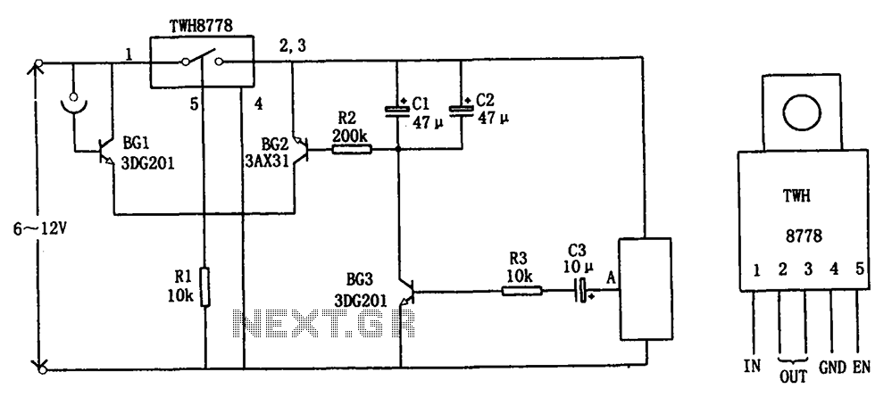
The circuit illustrated in FIG X pertains to automatic circuitry for US recorders. It primarily utilizes a new power switching device, TWH8778, which simplifies the design and eliminates the need for extensive debugging. The TWH8778's configuration and pin functions...
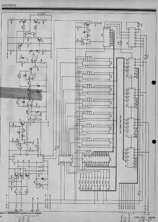
For approximately ten years, Texas Instruments has been developing solid-state speech technology that produces speech which accurately captures the characteristics of the spoken voice, including intonation, accent, dialect, and pitch. When connected to a microcomputer, it enables the formation...
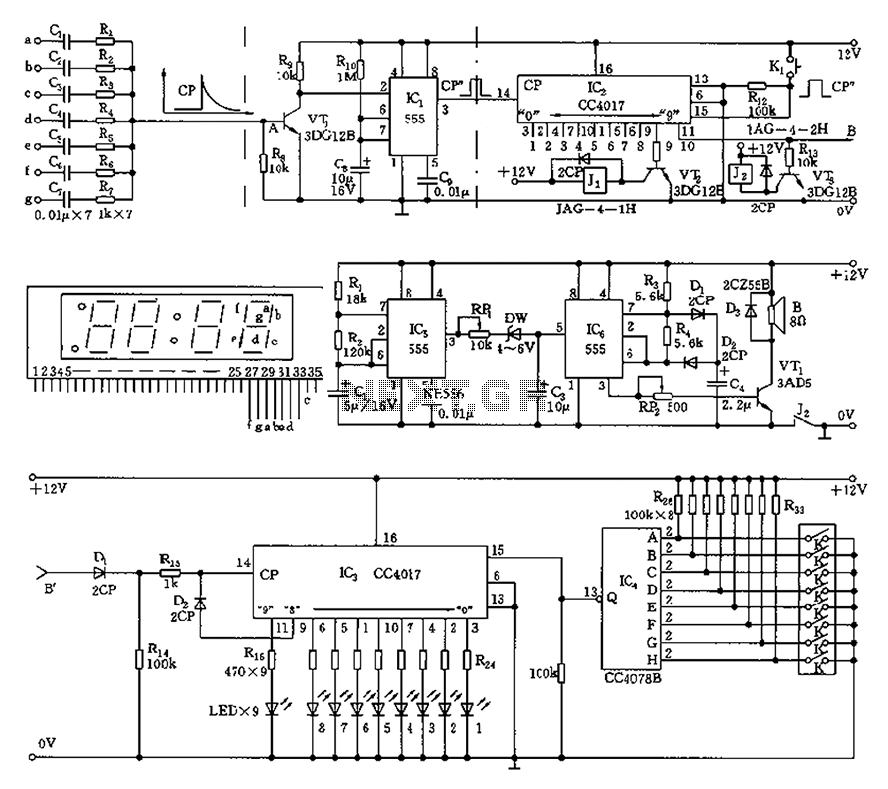
This circuit is primarily designed as a timely reminder system for monitoring individuals on duty who may fall asleep. It features a detection circuit that processes minute signals. As the LED digital electronic timing clock displays the minute, the...
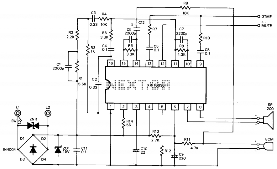
The XR-T5995 Speech Network is a monolithic integrated circuit specifically designed for implementing a low-cost telephone circuit. It is designed to use an electrodynamic microphone and electromagnetic receiver to replace a carbon microphone and telephone network hybrid. The XR-T5995 Speech...
KA2213 is a single-chip record and playback integrated circuit produced by Samsung in South Korea. It is utilized in audio recording and playback devices. The internal circuit block diagram and pin functions of the KA2213 include a record and...
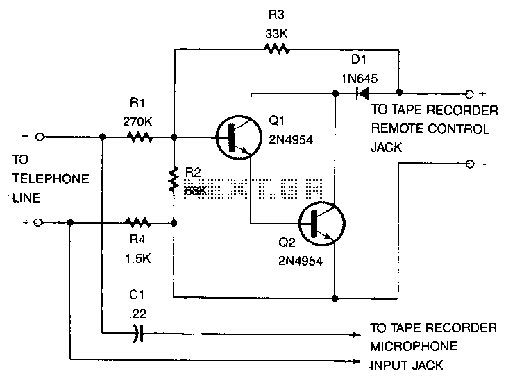
This recorder can be connected to telephone lines almost anywhere, and it does not require an external power source. The switch terminals of the tape recorder are connected to a pair of transistors configured as Darlington pairs, which are...