
Speed Alarm For Cars

This circuit functions as a speed alert system by utilizing a combination of components to monitor vehicle speed and provide audio feedback without the need for visual displays. The LM2917 frequency-to-voltage converter serves as the central processing unit, converting frequency signals from the speed sensor into a proportional voltage. This voltage is compared against preset thresholds defined by the trimpots, allowing for fine-tuning of the speed limits.
Transistor Q1 acts as an amplifier, ensuring that the speed pulses are adequately processed before being sent to the LM2917. The RC networks serve to filter and smooth the signals, providing stable input to the comparators. The SCRs act as electronic switches that momentarily conduct when their respective thresholds are exceeded, providing a clear and immediate response to the driver.
The use of trimpots allows for customization of the speed thresholds, accommodating different driving conditions or personal preferences. By setting the thresholds slightly above the actual speed limits, the circuit minimizes false alerts while ensuring that the driver is informed if they exceed safe speeds.
Overall, this circuit offers a practical solution to the challenges of speed monitoring in suburban driving, enhancing safety and convenience without the distractions of traditional speed displays.In normal suburban driving you pass through so many different speed zones that it can be a nuisance having to switch speed settings. The speed display can also be a distraction. This circuit eliminates the display and the need for speed selection. Each time you exceed a particular speed setting (eg, 40km/h, 50km/h, etc), a piezo buzzer will beep. Speed pulses are fed to the base of Q1 and the resulting waveform at its collector is fed via an RC network to the input of an LM2917 frequency-to-voltage converter, IC1. The resulting voltage is fed to three comparators (IC2d-IC2b) which have the reference voltages at their inverting inputs set by 10-turn trimpots VR1, VR2 & VR3.
The output of each comparator is applied via another RC network to the gate of an SCR. The anodes of the three SCRs are commoned connected to the inverting input of the remaining comparator, IC2a. Its non-inverting input is set to +2. 3V by trimpot VR4. In use, once you exceed the speed setting for a particular comparator, its associated SCR briefly conducts to pull pin 2 of IC2a low and a short beep is emitted by the piezo buzzer.
Then, as you exceed the next speed setting, another beep will be heard. The idea is make each speed setting a few km/h higher than actual so that if you are driving at the correct speed in a given zone, the buzzer will not sound. But as you increase speed, the buzzer will beep once as you exceed the speed setting for each zone. In this way, there is no need to continually switch speed settings as you drive through different zones and you can choose to ignore beeps that are not "illegal".
🔗 External reference
Related Circuits

The human infrared thermal release alarm can detect the infrared radiation emitted by the human body at any time of the day or night, triggering both sound and light alarms. This device is particularly suitable for electronic security applications....

The MIC5158 is part of a high-speed switching circuit diagram that focuses on the rising edge. The MIC5158 is a precision voltage reference and high-speed switching device that is commonly utilized in various electronic applications requiring rapid signal transitions. In...
This circuit includes a timed output and an automatic reset feature. It can be manually operated using a key switch or a concealed switch. By incorporating an external relay, the circuit will automatically engage or immobilize the machine each...

The alarm circuit operates as follows: When the power switch SW1 is turned on, the alarm system becomes active. If a magnet is brought close to the spring, the magnetic field attracts the spring, causing the dynamic and static...
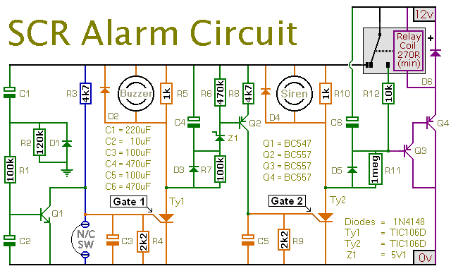
This is a simple SCR-based burglar alarm circuit. Its features include automatic exit and entry delays, along with a timed bell cut-off and reset. It is designed to be used with the usual types of normally-closed input devices such...
This circuit was designed to produce an audible alarm when the mains power is interrupted. Such an alarm is essential for anyone whose livelihood depends on continuous power supply. The circuit functions by monitoring the presence of mains voltage. It...