
A circuit diagram of a high-speed switch constituted triggered rising MIC5158

The MIC5158 is a precision voltage reference and high-speed switching device that is commonly utilized in various electronic applications requiring rapid signal transitions. In a typical high-speed switching circuit, the MIC5158 is integrated to ensure clean and fast rising edges, which are critical for maintaining signal integrity in high-frequency environments.
The circuit diagram featuring the MIC5158 typically includes several key components: the MIC5158 itself, resistors for setting the reference voltage, capacitors for filtering and stability, and possibly additional transistors or MOSFETs to drive larger loads. The rising edge of the signal generated by the MIC5158 is characterized by a swift transition from a low to a high state, which is essential for applications such as digital logic circuits, RF transmission, and high-speed data communication.
In the schematic, the input signal is fed into the MIC5158, which processes the signal to produce the desired output with a steep rising edge. The timing characteristics of the output can be adjusted by selecting appropriate external components, such as capacitors and resistors, which influence the charge and discharge rates of the internal circuitry.
Overall, the integration of the MIC5158 in high-speed switching applications enhances performance by reducing propagation delays and improving the overall responsiveness of the circuit, making it an invaluable component in modern electronic designs.MIC5158 constitute the rising edge of the high-speed switching circuit diagram.
Related Circuits
The tone generator was a straightforward project developed as a test unit for a customer design job. It utilizes two analog switches controlled by microprocessor code: one switch manages the signal directed to the operational amplifier that drives the...
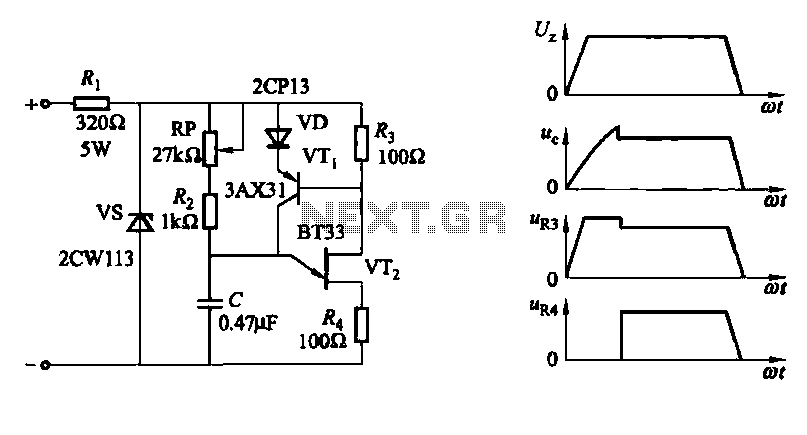
A conventional single junction transistor trigger circuit is limited to producing narrow pulses due to the rapid turn-off characteristics of the single-junction transistor. To address this limitation, a PNP transistor is added to the single-junction transistor trigger circuit, which...
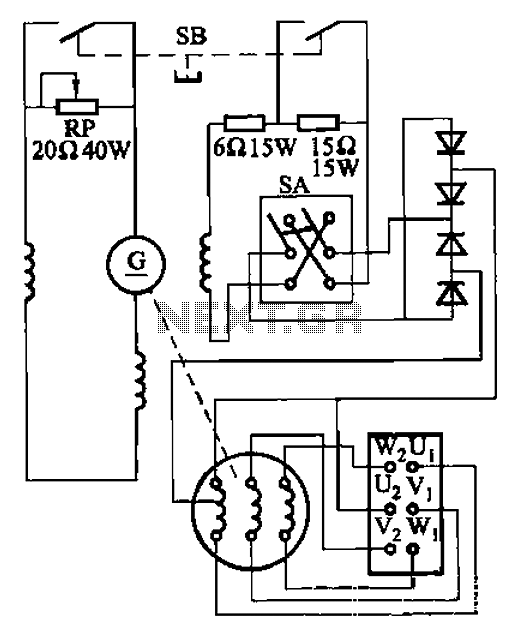
The AX3-300-2 DC arc welding machine circuit is part of the AX, AX1, AX3, and AR series of rotary DC arc welding machines. These machines share a similar structural design, featuring a three-integral unit configuration that combines an inverter...
The modern mechanic switches are improved concerning old technology. We need, however, many times to replace some old switch or to check currents bigger than the durability of certain switches or simply we need something with a modern appearance....
A circuit diagram of the T1 is a low-impedance output transformer, featuring a 5000-8 ohm resistor. The T1 low-impedance output transformer is designed to match the output of audio amplifiers to the impedance of loudspeakers, ensuring optimal power transfer and...

The schematic diagram below illustrates a basic sample-and-hold circuit utilizing the CA3140 as the readout amplifier for the memory capacitor. The CA3080A is also employed in the design. The sample-and-hold circuit is a crucial component in analog-to-digital conversion systems, allowing...