
square wave generator

The multivibrator circuit serves as a fundamental building block in electronics, providing a versatile tool for generating square waves and testing various components in radio repair applications. This project typically utilizes a configuration of transistors or operational amplifiers to create oscillations.
In a basic astable multivibrator configuration, two NPN transistors are connected in a feedback loop with resistors and capacitors that determine the frequency of oscillation. The circuit operates by alternately turning on and off each transistor, producing a continuous square wave output. The frequency of the output can be adjusted by varying the resistor and capacitor values, allowing the user to tailor the signal to specific testing requirements.
For practical implementation, the circuit can be built on a breadboard for easy modification and experimentation. The output can be monitored using an oscilloscope or a frequency counter to verify the oscillation characteristics. Additionally, the multivibrator can be used to test radio components such as capacitors, transistors, and diodes by observing their response to the generated square wave.
The accompanying how-to-use guide provides step-by-step instructions for assembling the circuit, including schematic diagrams, component lists, and troubleshooting tips. This project not only enhances understanding of basic electronic principles but also equips beginners with hands-on experience in circuit design and testing methodologies.an electronic project to build a multivibator as a basic first test instrument - ideal for trouble shooting radio repairs. Includes a how to use guide. An excellent beginner project.. 🔗 External reference
Related Circuits
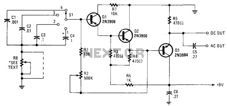
Seven narrow pulses ranging from 2 Hz to 50 kHz are generated by this circuit. Capacitors C1 through C4 provide frequency ranges in decode steps. Resistors R1 and R2 regulate the charging time of capacitors C1 through C4. R2...
The 555 Stepper Pulse Generator kit will help you with the pulse required to drive your favorite DC Servo Motor application. This kit uses the famous 555 timer IC for generating the Stepping Pulse. More: Input - 5 -...
This simple circuit generates a good and stable 1V peak-to-peak square wave at 100Hz, 1KHz and 10KHz using a single 1.5V cell as power supply. An useful feature of this circuit is that frequency changes can be obtained by...
This circuit generates a two-tone effect similar to the cuckoo song. It can be used for doorbells or other applications due to a built-in audio amplifier and loudspeaker. As a sound effect generator, it can be connected to external...
The approaches using on-chip A-to-D converters on AVR, PIC, and Cypress controllers reached sample rates of up to about 60 kHz. Not really very useful for the sort of thing I was thinking about using this for: encoded data,...
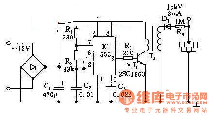
This high voltage generator is capable of producing a stable high voltage exceeding 8kV. The circuit design is straightforward, ensuring stability and reliability. It consists of a step-down rectifier, a voltage regulator circuit, an 18kHz multivibrator-type oscillator, and a...
Warning: include(partials/cookie-banner.php): Failed to open stream: Permission denied in /var/www/html/nextgr/view-circuit.php on line 713
Warning: include(): Failed opening 'partials/cookie-banner.php' for inclusion (include_path='.:/usr/share/php') in /var/www/html/nextgr/view-circuit.php on line 713