
Square wave oscillator

In electronic schematics, symbols represent various components and their connections within a circuit. A comprehensive understanding of these symbols and their functions is crucial for interpreting circuit diagrams effectively. Common symbols include resistors, capacitors, transistors, diodes, and integrated circuits, each serving a specific purpose in the overall design.
To facilitate understanding, it is essential to familiarize oneself with the standard symbols and their corresponding values. For instance, resistors are typically depicted as zigzag lines, while capacitors are represented by two parallel lines. Transistors can be more complex, often shown with additional connections indicating their type (NPN or PNP for bipolar junction transistors, for example).
In addition to symbols, recognizing the layout of the schematic is vital. Components are usually connected by lines that indicate electrical connections, and the arrangement often reflects the flow of current through the circuit. Understanding the function of each component within the context of the circuit is necessary to grasp how they interact to achieve the desired performance.
For those struggling with a specific schematic, it may be beneficial to break it down into smaller sections, analyzing each component and its role individually before considering the circuit as a whole. Utilizing resources such as online tutorials or reference books on electronics can also provide valuable insights into reading and interpreting schematics effectively.Well, I try to follow an instructable for quiet a while now, but I still couldn`t understand its schematic.. its not that I don`t know what the symbo.. 🔗 External reference
Related Circuits
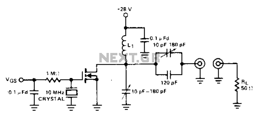
This crystal oscillator is a FET equivalent of a vacuum tube tuned to a plate-tuned grid crystal oscillator. Feedback is achieved through the drain to gate capacitance. The described crystal oscillator utilizes a Field Effect Transistor (FET) to replicate the...
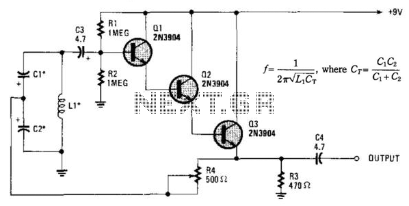
Essentially, this is a Hartley oscillator utilizing a triple-emitter follower, suitable for audio and low radio frequencies. The frequency is determined by the components, and at 1 kHz, a typical capacitor value would be 4.7 µF tantalum, although this...
For successful circuit-building exercises, follow these steps: Measure and record all component values before constructing the circuit, selecting resistor values that are sufficiently high to minimize the risk of damaging any active components. In case of significant errors (greater...
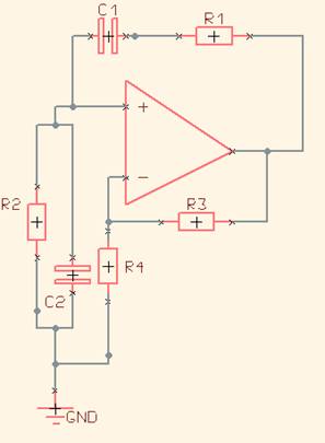
One of the simplest sine wave oscillators is the Wien Bridge Oscillator. Any circuit requires two conditions to oscillate. Tracing the path from the input, through the feedback network, and back to the input, there must be an overall...
This circuit generates a low power test signal and should not be used as a transmitter. Make sure you are within the law in the locality in which you operate this. As this was built from parts laying on...
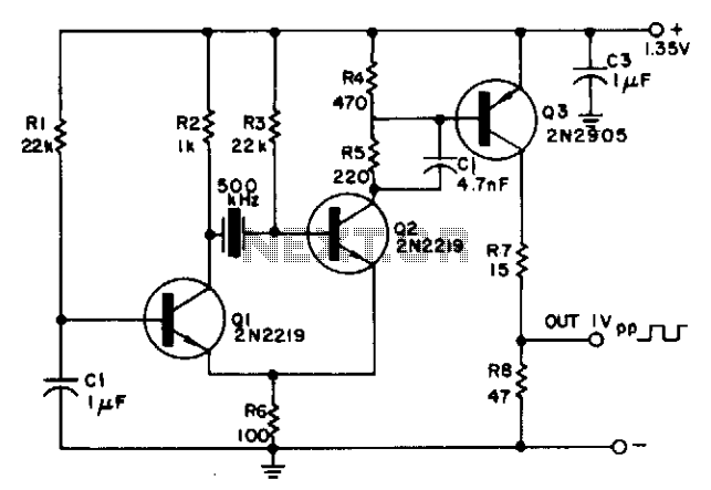
The circuit is powered by a single 1.35 V mercury cell and provides a 1 V square-wave output. The crystal acts as a tuned circuit between transistors Q1 and Q2, which are connected in a common-emitter configuration. Positive feedback...