
SSR Power Control Unit

The SSR Power Control Unit Circuit is designed to provide efficient control of electrical loads using solid-state relays, which offer advantages such as faster switching times, longer life spans, and reduced electromagnetic interference compared to traditional electromechanical relays.
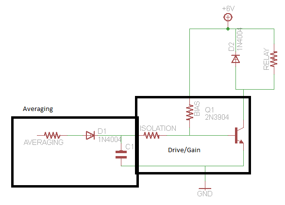
In this circuit, the SSR control box is the central component responsible for generating and supplying the necessary control voltage to activate the relay. The SSR operates by using semiconductor devices to switch the load on and off, allowing for precise control over the power delivered to the load.
Typically, the control voltage input to the SSR can be derived from a microcontroller or other control circuitry, which sends a low-voltage signal to the SSR. This signal is then used to trigger the relay, which in turn controls a higher voltage and current load. The SSR is characterized by its high input-to-output isolation, which ensures that the control circuit remains unaffected by the high voltage side of the system.
The circuit may include additional components such as resistors for current limiting, capacitors for noise filtering, and possibly opto-isolators to further enhance isolation and protect the control circuitry from voltage spikes. The layout of the circuit should be designed to minimize inductive and capacitive coupling, ensuring reliable operation in various electrical environments.
Overall, the SSR Power Control Unit Circuit is an essential design for applications requiring efficient and reliable control of high-power loads, providing an effective solution for automation and control systems in industrial and commercial settings.This circuit shows about SSR Power Control Unit Circuit Diagram. Features: SSR control box provides the control voltage for the relay. Component: . 🔗 External reference
Related Circuits
A circuit that activates a relay upon detecting audio pulses from one channel of an MP3 player. The intention is to synchronize recorded audio pulses with music to control a motor for mouth movement. For a stereo player, music...
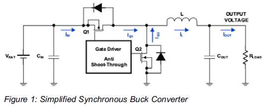
Increased Flexibility for Low-Power Synchronous Buck Converters. Contemporary synchronous buck converters designed for portable applications offer a power-save mode operation to sustain high efficiency throughout the entire range of operation. Modern low-power synchronous buck converters are essential components in portable...
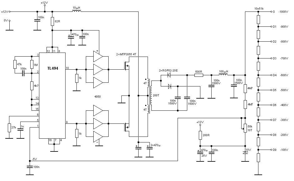
The schematic diagram originates from a circuit designed for a stable power supply ranging from -100V to -1000V. For further details, refer to the page that explains the circuit diagram associated with this power supply. This stable power supply...
This circuit is constructed around a 555 timer and utilizes very few components. Due to its simplicity, even beginners can easily assemble and use it as a control device. A readily available laser pointer can be employed to operate...
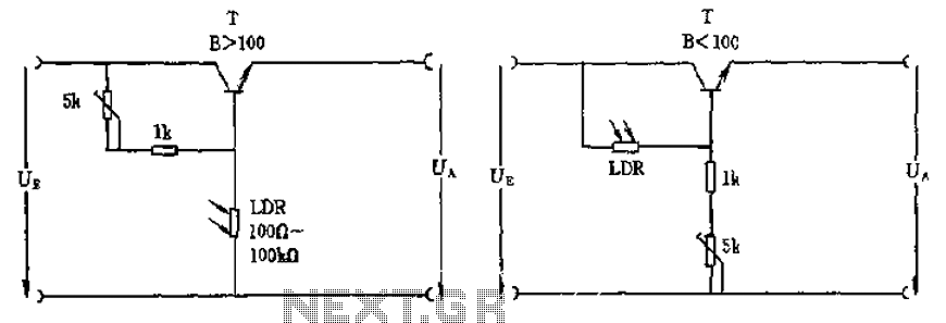
The circuit depicted involves a photoresistor (LDR) connected to a transistor, which operates at either a high or low level based on light conditions. The amplification factor of the transistor is 100, which is adequate for the application. The...
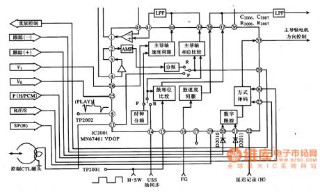
MN67641VDGF IC pin functions and data. MN67461VDGF IC's internal circuit block diagram and its typical application circuit. MN67461VDGF is a servo control IC produced by Panasonic, widely used in video cameras, such as the Panasonic NV-M8000 camera. Features: The...