
Stabilised amplifier schematic

The circuit utilizes the LT1052 and LT1028 operational amplifiers, which are known for their precision and stability. The LT1052 is a low-noise, high-speed operational amplifier, while the LT1028 is a precision, low-drift op-amp designed for applications requiring high accuracy.
The power supply requirements specify a dual ±15V output with a current capacity of 500mA. This configuration is essential for providing the necessary headroom for the amplifiers, ensuring that they operate efficiently within their specified voltage range. The dual supply configuration allows for both positive and negative signal swings, which is critical for amplifying AC signals or processing differential inputs.
In terms of circuit design, the ideal stabilized amplifier configuration would likely include feedback components to set the gain and bandwidth of the amplifier. Resistors and capacitors would be selected based on the desired frequency response and stability criteria. Proper bypass capacitors should be placed close to the power supply pins of the op-amps to filter out noise and ensure stable operation.
Thermal management is also a consideration, as the LT1028 can generate heat under high load conditions. Adequate heat sinking or thermal relief techniques may be necessary to maintain performance and reliability.
Overall, this circuit design provides a robust solution for applications requiring high-performance amplification, such as audio processing, instrumentation, or signal conditioning, leveraging the strengths of the LT1052 and LT1028 op-amps.It use the LT1052 and LT1028. Power supply should be double with +-15V 500mA. This is a ideal stabilised amplifier.
Related Circuits
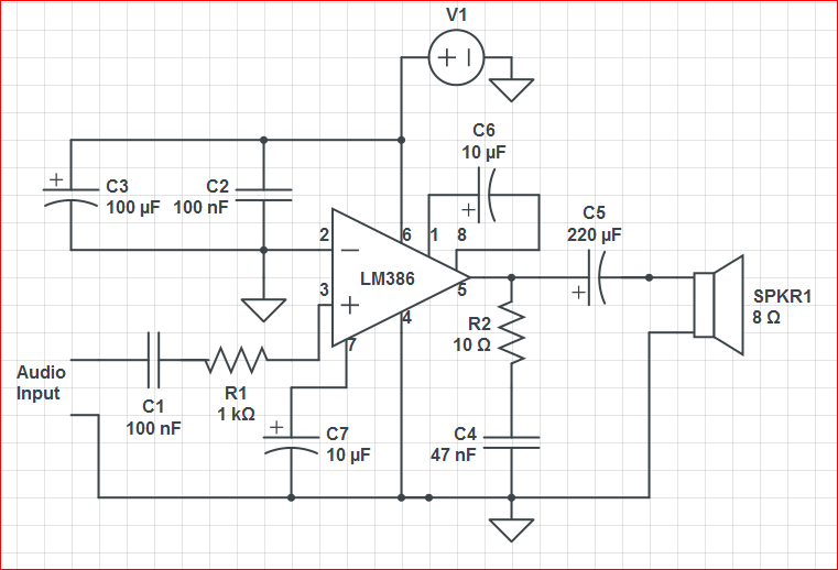
Initially, the circuit was connected to a 9V battery, which registered approximately 8.3 volts on a multimeter, within the operating voltage range for the LM386 as indicated in its datasheet. The output was characterized by significant noise, including crackling...
The circuit is designed to operate with an external power supply, which is why it does not include a transformer, rectifier, or filter capacitors in the schematic. However, these components can be added if desired. To utilize the circuit,...
This circuit employs an HgCdTe demodulation device that can be cooled to 77K using liquid nitrogen. It utilizes a constant current bias for the demodulation device, which is connected to the input port. The voltage amplification factor is 200,...
The hum noise is produced by an electronic device with improper design. To address this issue, it is essential to identify the source of the hum. This involves checking the grounding, cabling, casing, and other factors that may contribute...
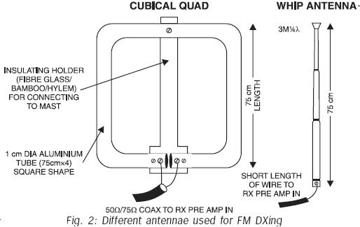
FM transmissions can be received within a range of 40 km. In fringe areas, the signal may be very weak. FM DXing refers to the practice of receiving distant stations (1500 km or more) on the FM band (88-108...
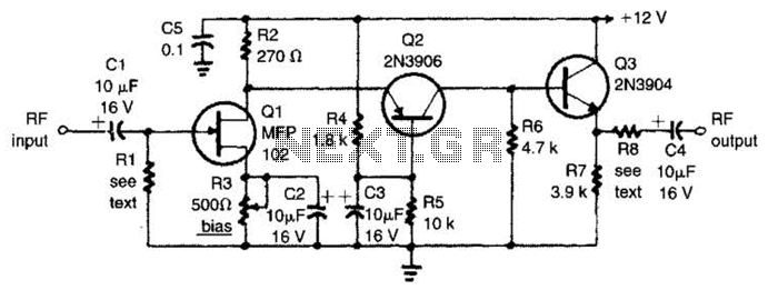
The circuit features a frequency response that spans from 100 Hz to 3 MHz, with a gain of approximately 30 dB. Field-effect transistor Q1 is arranged in a common-source self-biased configuration, and an optional resistor R1 is available to...