
Car battery charger Automative car and motorcycle schematics

The circuit operates by directly connecting to a power supply, which provides the necessary voltage and current for charging a battery. The absence of a transformer indicates that the circuit is designed for a specific voltage level, typically from a DC power supply. Users may consider incorporating a transformer and rectifier if AC power is used, which would allow for voltage adjustment and conversion to DC.
The charging mechanism is initiated by pressing the "Start" switch (S1), which completes the circuit and allows current to flow from the power supply to the battery. It is essential to ensure that the output terminals are correctly connected to the battery to prevent damage or inefficient charging.
Monitoring the circuit during its initial use is crucial, as it allows for the detection of any potential issues, such as overheating or excessive voltage, which could lead to battery damage or reduced lifespan. Implementing a simple voltage or current monitoring system can provide real-time feedback on the charging status, enhancing safety and efficiency.
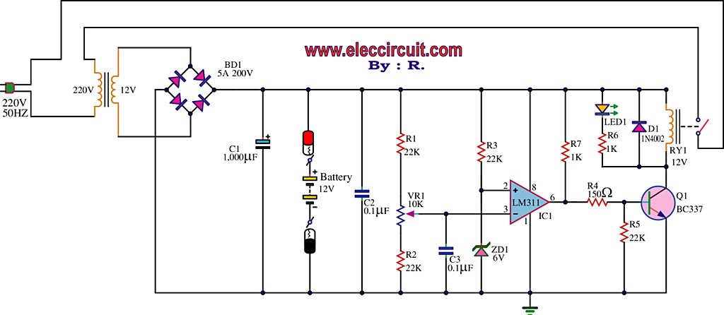
For added protection, users may consider integrating a charge controller or a battery management system (BMS) that can automatically regulate the charging process, prevent overcharging, and optimize battery health. These systems often include features such as temperature sensors and automatic shut-off mechanisms, which further enhance the reliability of the charging circuit.The circuit was meant to be powered by a power supply, which is why there is no transformer, rectifier, or filter capacitors on the schematic. There is no reason why you cannot add these. To use the circuit, hook it up to a power supply/plug it in. Then, connect the battery to be charged to the output terminals. All you have to do now is push S1 ( the "Start" switch), and wait for the circuit to finish. The first time you use the circuit, you should check up on it every once and a while to make sure that it is working properly and the battery is not being over charged. 🔗 External reference
Related Circuits
Using a magnetic compass, ensure that both pickups have a South polarity on the top of each pickup. Verify this by checking for a North polarity on the bottom of the pickups. It is uncommon to find both pickups...
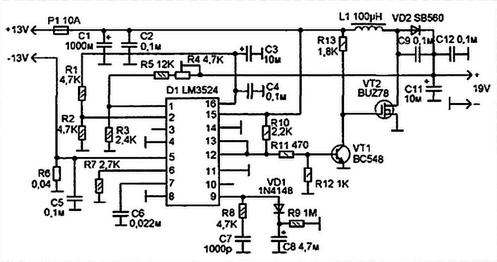
The best 12 Volt battery charger circuit is an automatic system that activates when the battery voltage falls below a specified threshold. This 12 Volt battery charger circuit is designed to efficiently charge lead-acid batteries while ensuring safety and longevity....
Laptops, commonly referred to as notebook computers, have gained significant popularity. Their portable design allows them to be easily transported in a bag, making them suitable for business trips and serving as convenient home entertainment centers due to their...
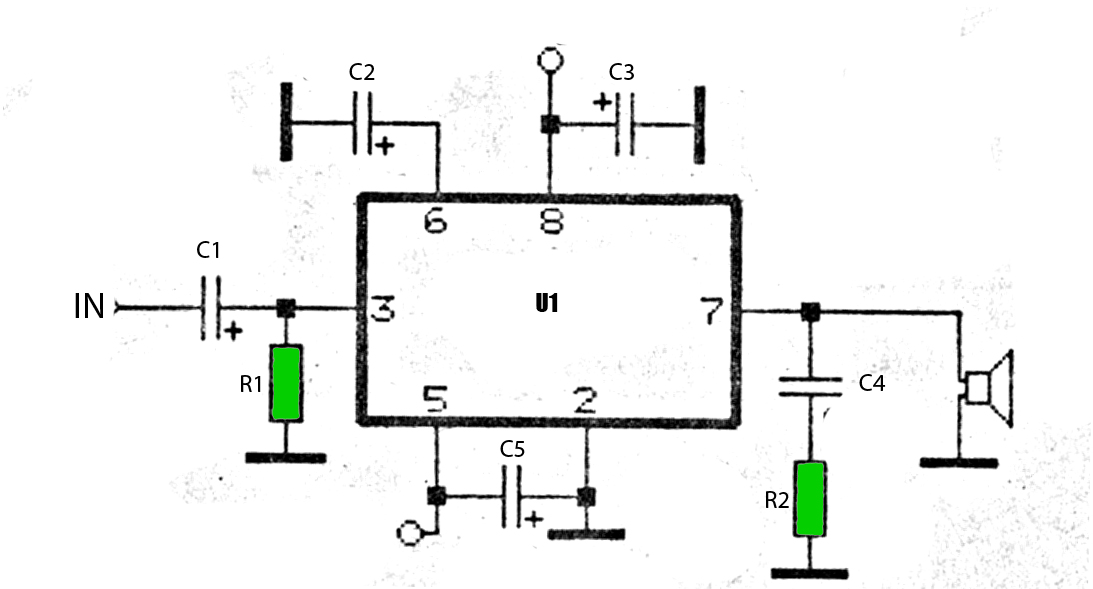
The car power amplifier utilizes the SI1050GL integrated circuit (IC) as the primary amplification component. It delivers an output power of 50 Watts at an 8-ohm mono impedance. The amplifier operates with a DC voltage of up to 25...
Switching to alternative power sources can help reduce electricity bills. The photovoltaic module or solar panel described here is capable of generating renewable energy. The photovoltaic module, commonly known as a solar panel, is a device that converts sunlight into...
The ZSSC1856 from ZMDI Company is a double-channel ADC integrated with an embedded MCU, composed of two chips packaged in a PQFN32 5x5mm format. The system's basic chip, the System Basis Chip (SBC), incorporates high voltage circuits, a LIN...