
Starting Network for Astable Multivibrator

An astable multivibrator is a fundamental electronic circuit that continuously switches between its two states without requiring any external triggering signals. This circuit is widely used in various applications, including clock generation, signal modulation, and timing applications.
The basic configuration of an astable multivibrator typically involves two resistors and a capacitor connected to a bistable multivibrator, often utilizing operational amplifiers or transistors. The resistors control the charge and discharge time of the capacitor, which in turn dictates the frequency of oscillation.
When the circuit is powered, the capacitor begins to charge through one resistor until it reaches a certain threshold voltage, at which point the output state changes from low to high. The capacitor then discharges through the second resistor, causing the output to switch back from high to low. This cycle continues indefinitely, resulting in a square wave output.
The frequency of oscillation can be calculated using the formula:
\[ f = \frac{1.44}{(R1 + 2R2) \cdot C} \]
where \( R1 \) and \( R2 \) are the resistances in ohms, and \( C \) is the capacitance in farads. The duty cycle, which determines the proportion of time the output is high versus low, can also be adjusted by varying the resistor values.
Astable multivibrators are commonly implemented in digital circuits for applications such as LED flashers, tone generators, and pulse width modulation (PWM) signals. Understanding the design and behavior of this circuit is essential for engineers working with timing and waveform generation in electronics.A flip-flop that generates two unstable states (high-low) is called astable multivibrator, a fancy name for you to say it`s an oscillator. The very basic of.. 🔗 External reference
Related Circuits
The astable flip-flop circuit is a versatile configuration used for creating flashers or generating square waves. A common application is an alternating LED flasher where the LEDs are connected in the emitters instead of the collectors, which is the...
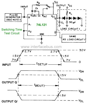
The pinout diagram for the 74L121 and 74L122 integrated circuits (ICs) is applicable to any style of 74xx121 or 74xx122 dual in-line package (DIP) chip, although the timing graphs are only relevant for the indicated TTL families. The 74121...
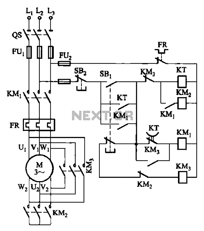
The circuit depicted in Figure 3-41 illustrates a Y-transfer process. When contact KMi is turned off, the motor undergoes a transition in the event of a power failure. Additionally, the main contact KM3 is disconnected when KM2 is activated,...
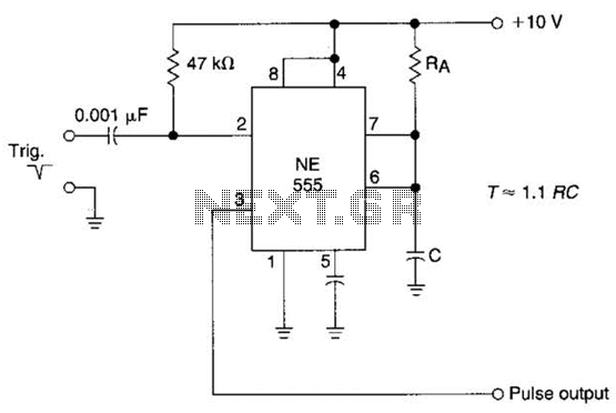
The time constant of RAXC determines the period of the monostable multivibrator. A negative pulse at pin 2 of the 555 starts the cycle. The monostable multivibrator is a circuit configuration that produces a single output pulse in response...
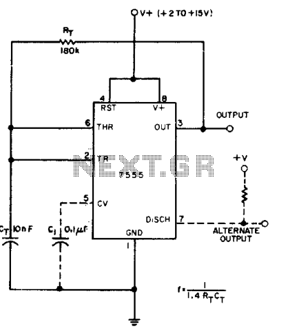
A CMOS timer generates true square waves because, unlike the bipolar 555, its output swings from rail to rail. The component values shown give a frequency of about 400 Hz. The CMOS timer circuit operates by utilizing complementary metal-oxide-semiconductor technology...
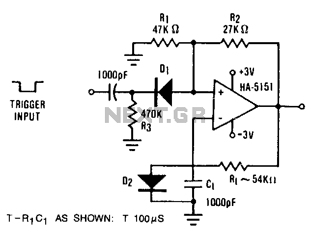
The circuit demonstrates the functionality of the HA-5151 as a battery-powered monostable multivibrator. In this configuration, the time constant is set to 0.632, simplifying the time constant equation to T = R1 * C1. Diode D2 is employed to...