
Cmos 555 astable generates square waves

The CMOS timer circuit operates by utilizing complementary metal-oxide-semiconductor technology to produce square wave signals with high precision. Its ability to swing from rail to rail means that the output voltage can reach the supply voltage levels, ensuring a full range of output states, which is particularly beneficial for digital applications.
In the described configuration, the timer's output frequency can be adjusted through the selection of external resistors and capacitors connected to the timing pins. The typical frequency of approximately 400 Hz indicates that the circuit is configured for moderate oscillation rates, making it suitable for applications such as flashing LED indicators or generating clock pulses for digital circuits.
The circuit typically includes two key components: a timing capacitor (C) and two resistors (R1 and R2) that set the charge and discharge times of the capacitor. The relationship between these components determines the frequency of oscillation according to the formula:
\[ f = \frac{1.44}{(R1 + 2R2) \cdot C} \]
This formula illustrates how variations in either resistance or capacitance will directly affect the output frequency. For instance, increasing R1 or R2 will result in a lower frequency, while increasing the value of C will also decrease the frequency. Conversely, decreasing these values will yield a higher frequency output.
The CMOS timer's design also minimizes power consumption compared to its bipolar counterpart, making it advantageous for battery-operated devices. The rail-to-rail output capability further enhances its versatility in interfacing with various logic levels, making it compatible with both TTL and CMOS logic families.
Overall, the CMOS timer is a robust choice for generating square wave signals in a wide range of electronic applications, providing reliable performance with adjustable frequency capabilities.A CMOS timer generates true square waves because, unlike the bipolar 555, its output swings from rail to rail. The component values shown give a frequency of about 400 Hz.
Related Circuits
A very long time constant is provided by R1 and C1. C1 discharges, and the near-zero voltage at its positive lead is applied to the high-impedance inputs of the circuit. In this circuit, the combination of resistor R1 and capacitor...
This mini metronome provides a linearly scaled output with a range of 40 to 208 beats per minute. The transistors Q1 and Q2 facilitate the linear frequency variation of IC1. The described mini metronome circuit utilizes an integrated circuit (IC1)...
This circuit is primarily designed as a timely reminder system for monitoring individuals on duty who may fall asleep. It features a detection circuit that processes minute signals. As the LED digital electronic timing clock displays the minute, the...
An oscillator is being developed to operate within the 200V range, targeting a frequency of approximately 1 kHz while minimizing current consumption. Initial testing has commenced. The design of a high-voltage oscillator capable of operating at 200V and generating a...
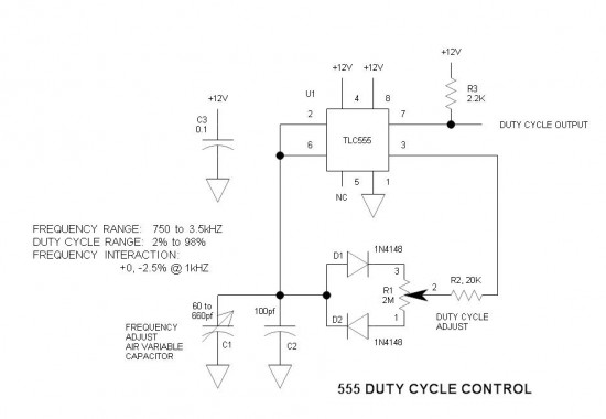
A simple oscillator circuit that varies the duty cycle over a wide range without affecting the frequency. It is a variation of the simple 555 astable oscillator. The use of an air-variable capacitor for frequency control is innovative. When...
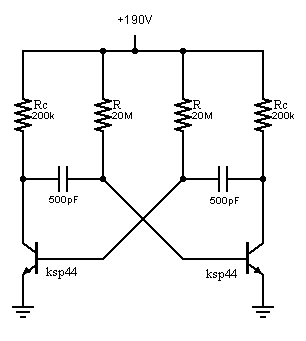
The basic bipolar transistor (BJT) version of an astable multivibrator has two outputs that repeatedly change state at a rate determined by the time constants of its feedback network. Although largely superseded by its equivalent op-amp or timer IC...