
Step sequencer
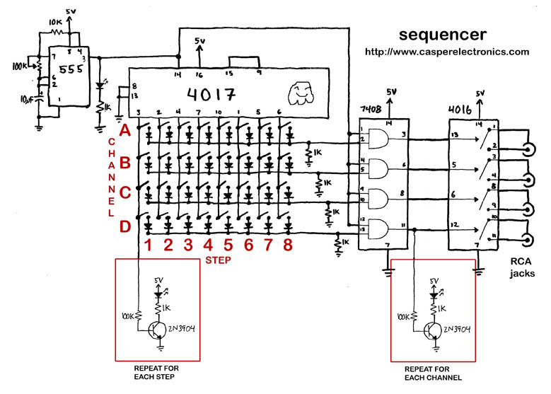
The 4017 Decade Counter is a versatile component in digital circuits, particularly useful for sequencing applications. It has ten outputs, each corresponding to a decimal count from 0 to 9, and provides a 100% duty cycle output, meaning that when a specific output is activated, it remains high for the entire clock cycle. This characteristic allows for the creation of overlapping sequences when multiple outputs are activated in succession. The 555 timer serves as a pulse generator, producing a square wave output with a 50% duty cycle, which is ideal for timing applications. The combination of these two components through an AND gate creates a hybrid output that leverages the strengths of both devices.
The AND gate ensures that the output is high only when both the 4017 and the 555 timer outputs are high, effectively controlling the timing of the sequencer steps. This configuration allows for precise timing control, as the 555 timer’s duty cycle can be adjusted to achieve desired timing parameters.
In terms of cascading two 4017 counters, this can be achieved by connecting the carry-out of the first counter to the clock input of the second counter. However, care must be taken to manage the timing and synchronization of the outputs, as propagation delays may affect performance, particularly in high-frequency applications.
The use of a Darlington pair to drive the 4017 outputs may simplify the circuit design but would indeed eliminate the 50% duty cycle feature, which could limit the versatility of the sequencer in certain applications.
When designing circuits that involve multiple components sharing a power supply, it is crucial to consider the power requirements and potential interference between devices. Overheating issues, such as those experienced with the 4016 chip, can often be mitigated by ensuring adequate power supply decoupling and possibly isolating components that draw significant current.
The CD4067 multiplexer could be an interesting alternative for expanding the number of steps in the sequencer, given its ability to handle multiple inputs. However, the lack of a reset feature may necessitate additional circuitry to manage the sequencing effectively.
The exploration of using toys or simple kits as random sequence generators presents a creative approach to sound design, allowing for unique and unpredictable outputs that can enhance musical compositions. Overall, the integration of these components requires careful consideration of timing, power management, and circuit design to achieve the desired functionality in electronic sequencing applications.The output of the 4017 is 100% duty cycle. so that means if you have step one and step two on, they will lead right into each other and you`ll have a step that is 2 cycles long. The output of the 555 timer is a 50% duty cycle. The AND gate combines the outs of the 4017 and the 555. The out of the AND is only high when both the 4017 and t he 555 are high. SO it will go high when you set the step switch (from the 4017 out) on and for half a cycle because of the 555 50% duty. Make sense It`s kind of confusing but relatively simple as far as logic goes. Does this schematic actually work I would imagine there is some propagation delay through the decade counter that will prevent the clock signal from lining up with the pulse from the counter at the AND gates any comments on this is long enough that even if they start a few nanoseconds off it doesn`t matter.
In a musical context any delay is completely imperceivable. If the sequencer was running at extremely high frequency it might be an issue. Hi, ive been casually working on designs for a sequencer for quite a while (too long!). I want one to trigger where the piezos normally would on my electric drum. I was after more steps so ive tried (unsuccessfully) to cascade two 4017 ²s. A new thought occoured to me maybe they could be driven by the two outputs of a darlington pair. This would`nt allow the 50% duty cycling thing (which might be a problem) but would be a nice tidy circuit! I am working on a tutorial for Make Magazine right now. It will include step by step directions on how to build one from scratch. I will post the instructions on my site once they are done. casper, thanks for all of this information! 2 questions: will this sequencer allow two channels to be activated at the same time also, can multiple sequencers use one 555 clock without making problems can`t wait for MAKE 27!
btw. I can`t seem to make the circuit do the long 100% cycle. I`ve put the switch where illustrated in the layout, but when i switch it, it stops triggering all together. Any ideas another thing. I`ve burnt one channel on one 4016 chip by connecting a homebrewed distortion pedal in series after the toy triggered by the sequencer.
I don`t really get what the problem is, other than it doesn`t like (the 4016 gets really hot) sharing the same power supply as the distortion pedal. Any ideas on that one I`m inclined to say YES you could use a CD4067. I havent used that chip so I`m not overly familiar with its functionality but it seems to be a counter.
I guess its big limitation is that it doesn`t have a reset feature but it is conveniently 16 steps. Hmmmm. Worth experimenting with. Just a thought here. Maybe a useless idea but, I was looking at a Toybiz Whack-a-Mole game and was thinking that it, or something like it, might make a good random sequence generator. The idea being to trigger different bends for my drum machines to get a Illformed Glitch VST style effect.
There may be problems with the toy expecting user feedback to continue the patterns. Ah, I see what you did there. It`s much like those Radioshock LED kits. I picked one up to use maybe for my bend sequencer. I got the Velleman MK152RS LED wheel. Didn`t realize the MK107 was the kit of choice for a sequencer. Anyone have tips on how to use the MK152RS for a bend sequencer Hi casper, i`m actually thinking about making an 8 step sequencer for my toys, because playing three toys or more alone is impossible. But when i saw your schematic (the one with the 74HC08 IC), i had a reflexion : is it possible to add more channels (mmh 6 or 8 instead of four) following the same schem Did you ever try
🔗 External reference
Related Circuits
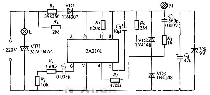
The BA2101 is a dimming controller utilizing an ASIC to create a barrel of light touch stepping. It is a non-constant lamp suitable for heir light. Each touch on the electrode sheet M can adjust the lamp brightness through...
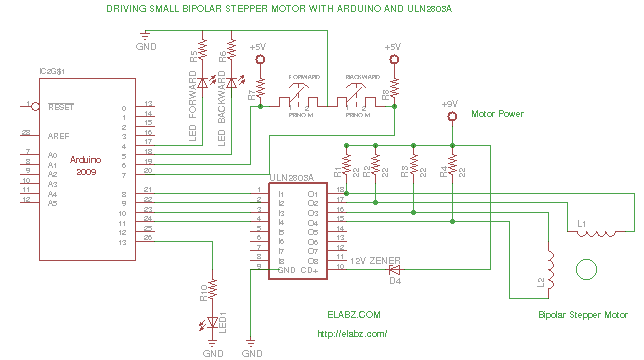
While preparing to disassemble several broken DVD-RW drives obtained from an eBay seller, the idea arose to create a testing platform for the bipolar stepper motors that would be salvaged from these drives. A collection of ULN2803AG Eight Darlington...

After extensive searching online, a 16-step sequencer schematic was not found that did not require an Arduino, PIC, or another digital controller. A simple 3-chip analog 16-step sequencer with variable speed and arpeggio has been developed, drawing from various...
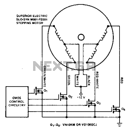
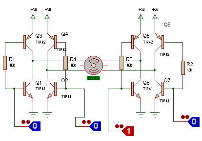
Stepping motors are commonly utilized in disk drives and machine control applications. MOSPOWER transistors serve as excellent motor drivers due to their immunity to second breakdown. It is important to note that snubbing networks are unnecessary since load line...
A bipolar motor is being utilized, along with software developed for the PIC 12F508 microcontroller, which is intended for driving a unipolar motor. The correctness of the attached schematic for this application is in question. The use of a...
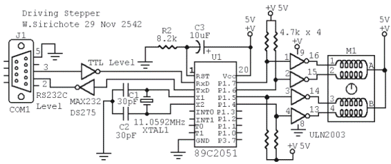
M1 is a stepper motor salvaged from an old disk drive. It features five pins: common, coil 1, coil 2, coil 3, and coil 4. The resistance measured between the common pin and each coil is approximately 75 Ohms....