
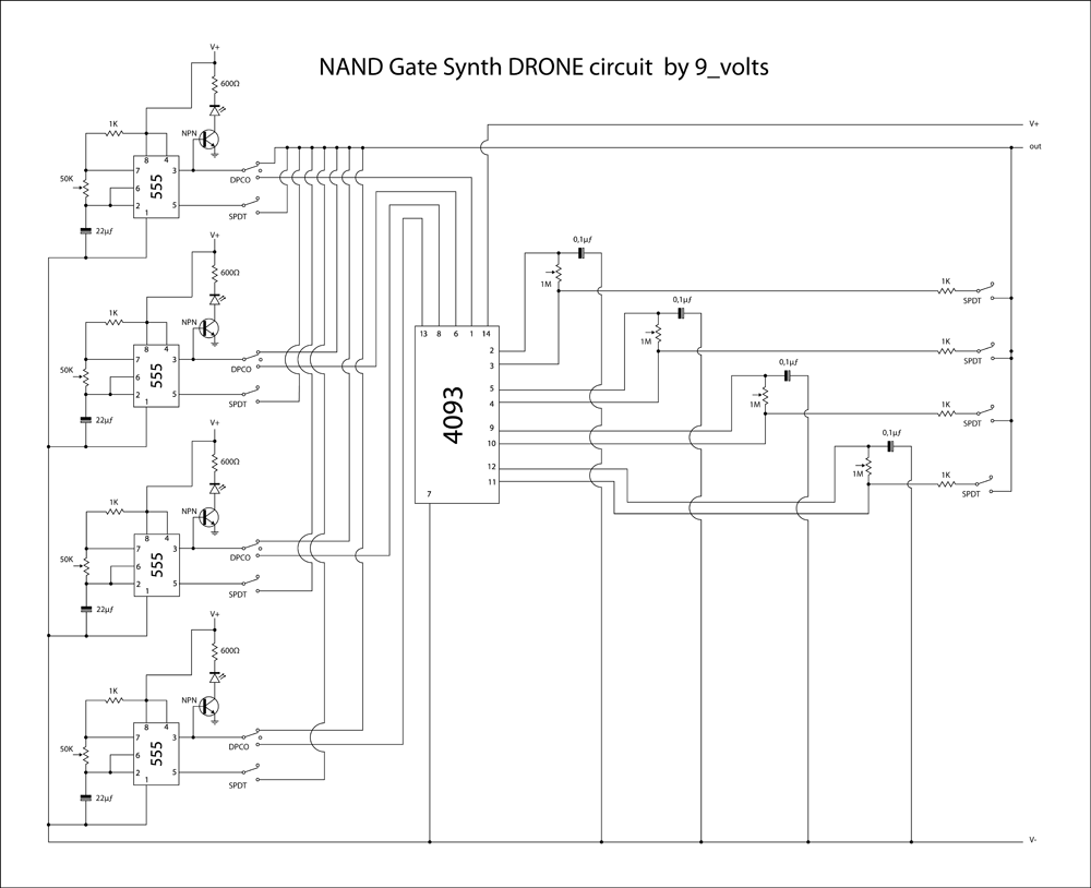
16 step sequencer schematic

The described 16-step sequencer utilizes three integrated circuits to create a fully analog system capable of generating complex sequences without relying on digital controllers. The primary component, the 4015 dual 4-bit shift register, enables the storage and manipulation of step data. Each of the two registers can hold a sequence of four bits, allowing the sequencer to produce a total of 16 distinct steps. The variable speed control can be implemented using a variable resistor or potentiometer connected to the clock input of the 4015, enabling users to adjust the tempo of the sequence dynamically.
The design also incorporates an arpeggio function, which can be achieved by manipulating the output of the shift registers to create ascending or descending patterns based on the input voltage levels. This feature can be useful for musical applications, allowing for more expressive and varied output.
It is crucial for builders to pay attention to the capacitor connections, as incorrect polarity can lead to circuit failure. Capacitors should be oriented according to their markings, with the negative lead connected to ground or the lower voltage side of the circuit. Understanding the pin configuration for the 4015 is also essential, as this will determine how the shift registers are wired and how the sequencer operates.
The additional illustrations, such as the previously mentioned 8-step sequencer, serve as valuable references for understanding the layout and connection of components. They provide insights into the necessary parts, including the CV output potentiometer and plugs, which are crucial for interfacing the sequencer with other devices or synthesizers. By studying these diagrams, builders can gain a comprehensive understanding of how to construct a reliable and functional analog sequencer.After a lot of searching the web, I could not find a 16 step sequencer schematic that didn`t require an arduino or PIC or some other digital controller. Here is a simple 3 chip analog 16 step sequencer with variable speed and arpeggio I came up with, based off many other inspirations as noted in the file.
The I Cs in the middle are pin-diagrams, arranged like this since a 4015 is actually two 4-bit shift registers in each chip, so each 4015 has 16 pins but the IC numbers indicate IC1 and IC2 (IC = integrated circuits, AKA chips. ) If you`re new at building sequencers, make sure to learn how to tell the polarity of capacitors connections and the way to figure out pins.
Check my other illustration ( 8-step sequencer ) for diagrams and other important parts listed of a fully functioning machine. For example, the CV output pot and plugs are described in more detail on that schematic but not here.
🔗 External reference
Related Circuits
Here is a little audio amplifier similar to what you might find in a small transistor radio. The input stage is biased so that the supply voltage is divided equally across the two complimentary output transistors which are slightly...
In addition to its primary function as a headphone amplifier, this circuit is applicable in various scenarios requiring a wide bandwidth low power amplifier. It utilizes an operational amplifier (op-amp) with its output current enhanced by a pair of...
This is a brief jam session to explore the capabilities of a recently completed step sequencer. This device is quite enjoyable and expands creative possibilities. A detailed post with the circuit and instructions for building it will be provided...
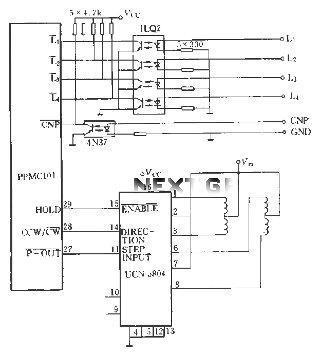
The PPMC external UChl 5804 demonstrates a four-phase stepping motor drive integrated circuit (IC) that is depicted in a downward motion. It utilizes the P-OUT, counterclockwise (ccw) / clockwise (cw), and HOLD outputs. The UCN5804 pins 9 and 10...
The circuit employs two Light Dependent Resistors (LDRs) arranged in series with a separation of approximately half a meter. This configuration allows each LDR to detect the presence of a person entering or exiting the room. The processed outputs...
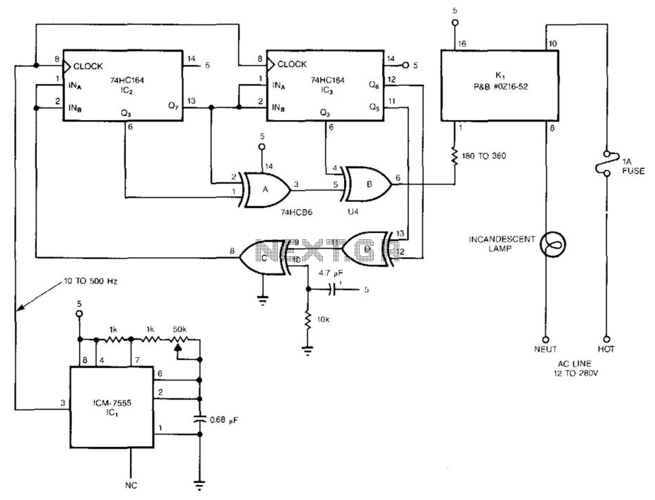
The pseudorandom sequencer drives a solid-state relay. When a low-wattage lamp is powered from the relay, the lamp will flicker like a candle's flame in the wind. Using higher-wattage lamps allows for the simulation of a fireplace or campfire...