
Stepper Motor ControllerCircuit Based On The 7404 IC

The stepper motor controller circuit utilizing the 7404 IC is designed to drive a stepper motor with a straightforward and efficient approach. The 7404 IC, a hex inverter, plays a crucial role in generating the necessary control signals for the stepper motor operation.
In this configuration, the circuit typically includes the following components: the 7404 IC, a power supply, the stepper motor, and additional passive components such as resistors and capacitors for signal conditioning. The power supply provides the required voltage and current to both the 7404 IC and the stepper motor, ensuring reliable operation.
The stepper motor is controlled by sending a sequence of pulses to its windings, which are managed by the output of the 7404 IC. The inverters in the IC convert the input control signals into the appropriate logic levels needed to energize the motor phases in the correct order, allowing for precise control of the motor's position and speed.
Additionally, the circuit can be enhanced with features such as speed control through pulse width modulation (PWM) or the inclusion of a microcontroller for more complex control schemes. Implementing such features can significantly improve the performance and versatility of the stepper motor controller, making it suitable for various applications in robotics, automation, and precision positioning systems.
Overall, this stepper motor controller circuit exemplifies a basic yet effective method of controlling stepper motors using the 7404 IC, showcasing simplicity and functionality in electronic design.The following circuit shows about Stepper Motor Controller Circuit Diagram. This circuit based on the 7404 IC. Features: simple stepper motor . 🔗 External reference
Related Circuits
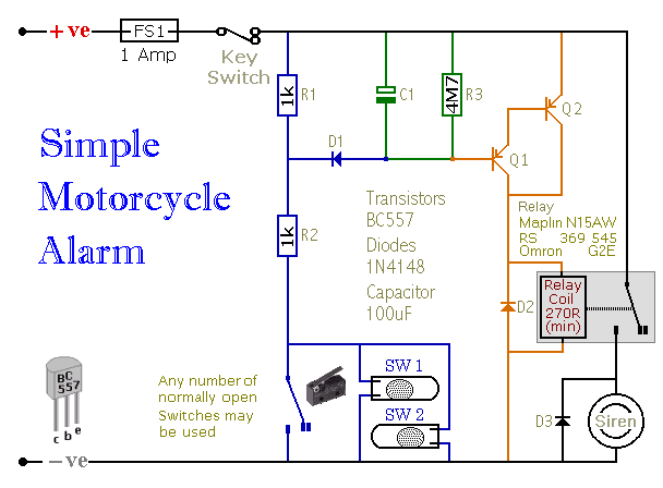
When one of the switches is closed, the base of Q1 is connected to ground through D1 and R2. This activates Q1, which in turn activates Q2. Q2 connects the positive side of the relay coil to the supply...
The capacitor charges until the PNP transistor (here shown as a 2N3906, but you could also use a BC327) receives base current through the Zener and turns on. Then the NPN transistor (here shown as a 2N3904, but you...
This design is intended as a dimmer for a 12V reading lamp, but it can also function as a motor speed controller for devices like drills. The circuit modulates the voltage supplied to the load, allowing for variable pulse...
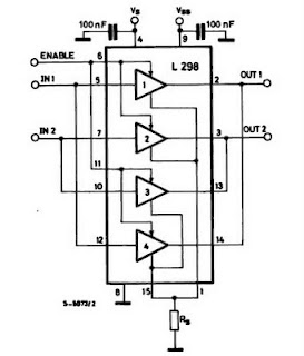
The IC H-Bridge DC motor driver L298 contains two H-Bridge circuits, allowing it to drive two DC motors simultaneously. Each H-Bridge circuit can deliver currents up to 2A. When used in parallel, the L298 can provide a total current...
The program utilizes two pulse width variables, pw1 and pw2, along with two sets of routines—left1 and left2, and right1 and right2—designated for each motor. The schematic illustrates that the first servo is connected according to the previous circuit...
A PIC16x84 processor can be utilized to generate a PSK31 or FSK31 signal. This signal may serve various purposes, including beacon transmissions, telemetry, experimentation, or QSOs, though the latter may involve some quirks. The PSK transmitter was initially designed...