PIC-based PSK31 MedFer Beacon

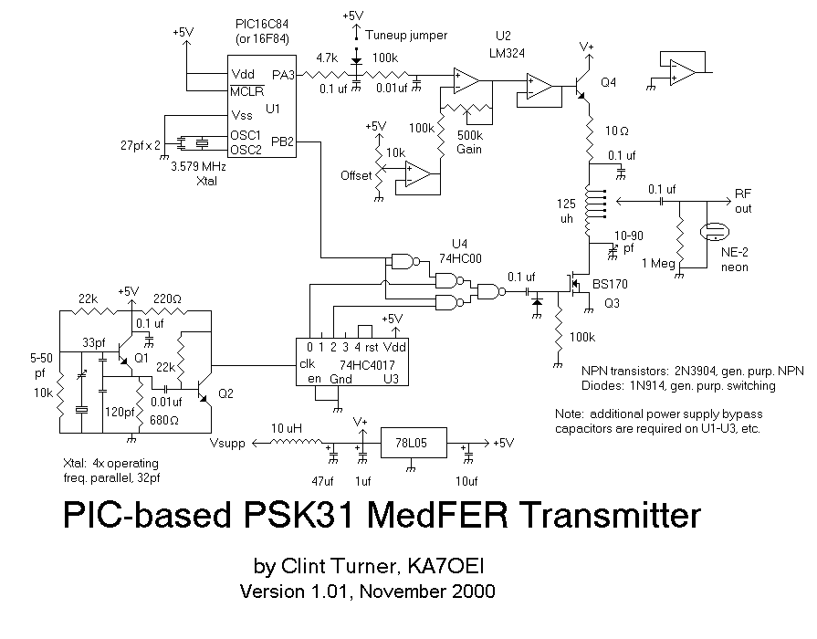
A PIC16x84 processor can be utilized to generate a PSK31 or FSK31 signal. This signal may serve various purposes, including beacon transmissions, telemetry, experimentation, or QSOs, though the latter may involve some quirks. The PSK transmitter was initially designed in 1999 for the now-discontinued PIC16C84, but it has since been updated for the still-available PIC16F84. Numerous newer PICs have been released that could enhance the capabilities and performance of this unit, although no updates have yet been made. The source code is accessible, making it relatively easy to port it to a newer chip. Operating beacons previously has demonstrated that minimizing the hassle factor increases the likelihood of keeping the beacon operational. When establishing a PSK31 MedFER beacon, the goal was to create a device that could send messages in PSK31 and function upon connection. The design incorporates the widely used PIC processor along with simple circuitry. Version 1.0 offered basic beacon functionality by playing messages stored in EEPROM, requiring reprogramming to change messages. Version 2.0 maintains backward compatibility while also enabling remote control and EEPROM loading via a 1200 baud RS-232 port. A balanced modulator is a suitable solution for modulating both amplitude and phase, essential for PSK31; applying RF and the correct baseband modulating signal yields the desired output. This can be achieved using a diode modulator or an integrated circuit like the `1496. While this method effectively generates low-level RF signals, linear amplification is necessary to produce higher RF power. For LowFER or MedFER beacons where transmitter efficiency is crucial, linear amplifiers may result in 1-2 dB lower output power compared to a high-efficiency switching-type power amplifier. A prototype "balanced modulator" exciter is documented, including a schematic and images. Instantaneously shifting the carrier phase by 180 degrees, such as using an XOR gate for BPSK modulation, can produce significant sideband energy. To mitigate clicking, reducing power to zero during the phase shift and then returning it to normal using a cosine envelope can be employed, allowing for the use of an efficient but nonlinear power amplifier. This approach is reminiscent of the HELAPS (High Efficiency Linear Amplification using Parametric Synthesis) scheme originally developed by AMSAT for the OSCAR spacecraft, which required maximum power efficiency.
The circuit design for the PSK31 or FSK31 signal generation using the PIC16x84 processor involves several key components and considerations. The PIC16x84 serves as the central processing unit, executing the programmed instructions to generate the desired modulation scheme. The microcontroller interfaces with an EEPROM to store the messages that will be transmitted. The circuit typically includes a power supply section to ensure stable operation, often utilizing a voltage regulator to maintain the necessary voltage levels for the PIC and other components.
The modulation process is facilitated by a balanced modulator, which can be implemented using discrete components or an integrated circuit. The choice of a balanced modulator allows for effective manipulation of both amplitude and phase, which is crucial for generating PSK31 signals. The output of the modulator feeds into a linear amplifier stage, which amplifies the RF signal to the required power level for transmission. The design must account for the efficiency of the amplifier, particularly in LowFER or MedFER applications, where compliance with regulatory power limits is essential.
Additionally, the inclusion of an RS-232 port for remote control and EEPROM programming adds versatility to the design. This allows users to modify the transmitted messages without direct access to the hardware, enhancing operational convenience. The design should also incorporate filtering components to minimize unwanted harmonics and ensure signal integrity.
Overall, this circuit design emphasizes ease of use, efficiency, and adaptability, making it suitable for various applications in amateur radio and telemetry. The combination of the PIC16x84 processor, balanced modulation techniques, and efficient amplification strategies creates a robust platform for PSK31 and FSK31 signal generation.A PIC16x84 processor may be used to generate a PSK31 or FSK31 signal. This could be used for beacon transmissions (as described here) or they may be used for telemetry, experimental, or even QSOs - the latter being true if you are willing to put up with a few "quirks":-) The PSK transmitter was originally designed back in 1999 - originaly for the now-discontinued PIC16C84, but later updated for the PIC16F84 which is still available. Since then, however, a large variety of newer PICs have been released that could be used to significantly expand the capabilibities and performance of this unit - but I`ve not done so. Since the source code is available to all, "porting" it to one of these new chips would be pretty easy.
This is the question that I asked myself. While my HF rig is capable operating in the MedFER frequency range, it seemed foolish to tie it up in this fashion, and it would tie up an entire computer/sound card/ect. Having operated beacons in the past, I feel that the lower the "hassle factor" involved in operating the beacon, the more likely it is that you will keep it on the air - and that is the entire purpose of even attempting to operate a beacon.
When I decided to put a PSK31 MedFER beacon on the air this time around, I decided to follow my previously-established philosophy: I wanted a beacon that could send a message in PSK31, and just work when plugged in. To generate the PSK31 data, I decided to utilize the now-ubiquitous PIC processor and incorporate it with other fairly simple circuitry.
(As for the question of "why operate a beacon, anyway " - I don`t really have a good answer. Take a look at the "CT" Lowfer Beacon archive page for a possible insight as to the psychology of it all. ) Version 1. 0 provided simple beacon operation, simply playing its message out of EEPROM. It required reprogramming of the PIC`s on-board EEPROM in order to change the message. The source code, a description of the code, and a. HEX file is described here. Version 2. 0 provides for completely backwards compatible operation (i. e. it has a mode that is indistinguishable from the Version 1. 0 operation) PLUS it allows for remote control/EEPROM loading via a 1200 baud RS-232 port. Using a balanced modulator is an obvious solution: It can modulate both amplitude and phase in exactly the way that is required for PSK31: One need only apply RF and the appropriate baseband modulating signal and the result is a PSK31 signal.
This can be done with either a diode modulator (a singly or doubly-balanced modulator) or an IC of similar function, such as the venerable `1496. This method works well to generate low-level RF signals, but linear amplification is necessary to develop additional RF power.
If, as in the case of a LowFER or MedFER beacon, transmitter efficiency is highly important (keep in mind that Part 15 specifies input power and not output power!) linear amplifiers would result in 1-2 db lower output power than could be obtained from a high efficiency switching-type P. A. A description of the prototype "balanced modulator" exciter (with schematic and pictures) is available here.
Simply shifting the phase of the carrier by 180 degrees instantaneously (i. e. using an XOR gate for BPSK modulation) results in the generation of considerable sideband energy (i. e. clicking. ) If one were to lower the power to zero, do the phase shift, and then return the power to normal (using a cosine envelope to do the modulation, ) the effect of the click is eliminated and one may use an efficient (but nonlinear) power amplifier. This scheme is used on the transmitter described below. In the simplest sense, this modulation scheme somewhat resembles the HELAPS (High Efficiency Linear Amplification using Parametric Synthesis) scheme devised originally by AMSAT for use on the OSCAR spacecraft where the highest power efficiency was required in that the amp
🔗 External reference


